SM 60 specifications
The Bush Hog SM 60 is a versatile and durable rotary mower designed primarily for use in agricultural and landscaping applications. Known for its robust construction and exceptional performance, this machine is ideal for managing grass, brush, and overgrown vegetation, making it a valuable asset for farmers, ranchers, and landowners alike.One of the main features of the Bush Hog SM 60 is its cutting width, which measures 60 inches. This allows for efficient mowing of large areas, reducing the time spent on maintenance tasks. The mower is equipped with a heavy-duty gearbox that provides reliable power transmission while enhancing its overall durability. This ensures that the SM 60 can handle tough mowing conditions with ease.
The design of the Bush Hog SM 60 incorporates a sturdy frame made from high-quality materials, which provides stability and strength. The mower is built to withstand harsh environments and frequent use, ensuring long-lasting performance. Additionally, the SM 60 features a reinforced deck that helps to prevent soil buildup and maintains clean, efficient cutting.
Technologically, the Bush Hog SM 60 is equipped with a set of three high-lift blades that are designed for superior cutting performance. These blades facilitate efficient grass distribution, resulting in a clean cut that promotes healthy regrowth. Furthermore, the blade design reduces the risk of clumping, which is especially crucial in wet conditions.
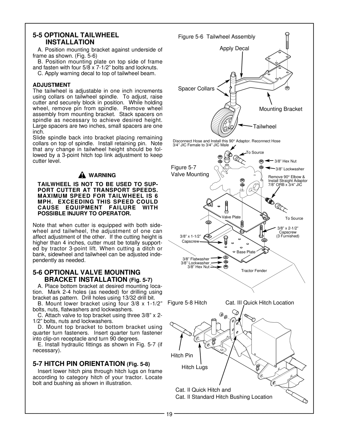
Another noteworthy characteristic of the SM 60 is its adjustable cutting height. Users can easily modify the height of the mower to achieve the desired level of cut, providing flexibility for different mowing conditions and types of vegetation. This feature is particularly beneficial when transitioning between various terrains, ensuring optimal performance no matter the situation.
The Bush Hog SM 60 is designed to be compatible with a variety of tractors, making it a versatile tool for any operator. Its ease of attachment and operation allows users to quickly switch from one implement to another, enhancing overall productivity.
In summary, the Bush Hog SM 60 is a powerful rotary mower that combines durability with efficiency. Its impressive features, including a wide cutting deck, robust construction, and high-performance blades, make it an exceptional choice for anyone in need of a reliable mowing solution. Whether it's for maintaining pastureland, managing brush, or enhancing landscape aesthetics, the Bush Hog SM 60 stands out as a top-tier option in the rotary mower market.

