LANVIEW LEDs
Table
Table
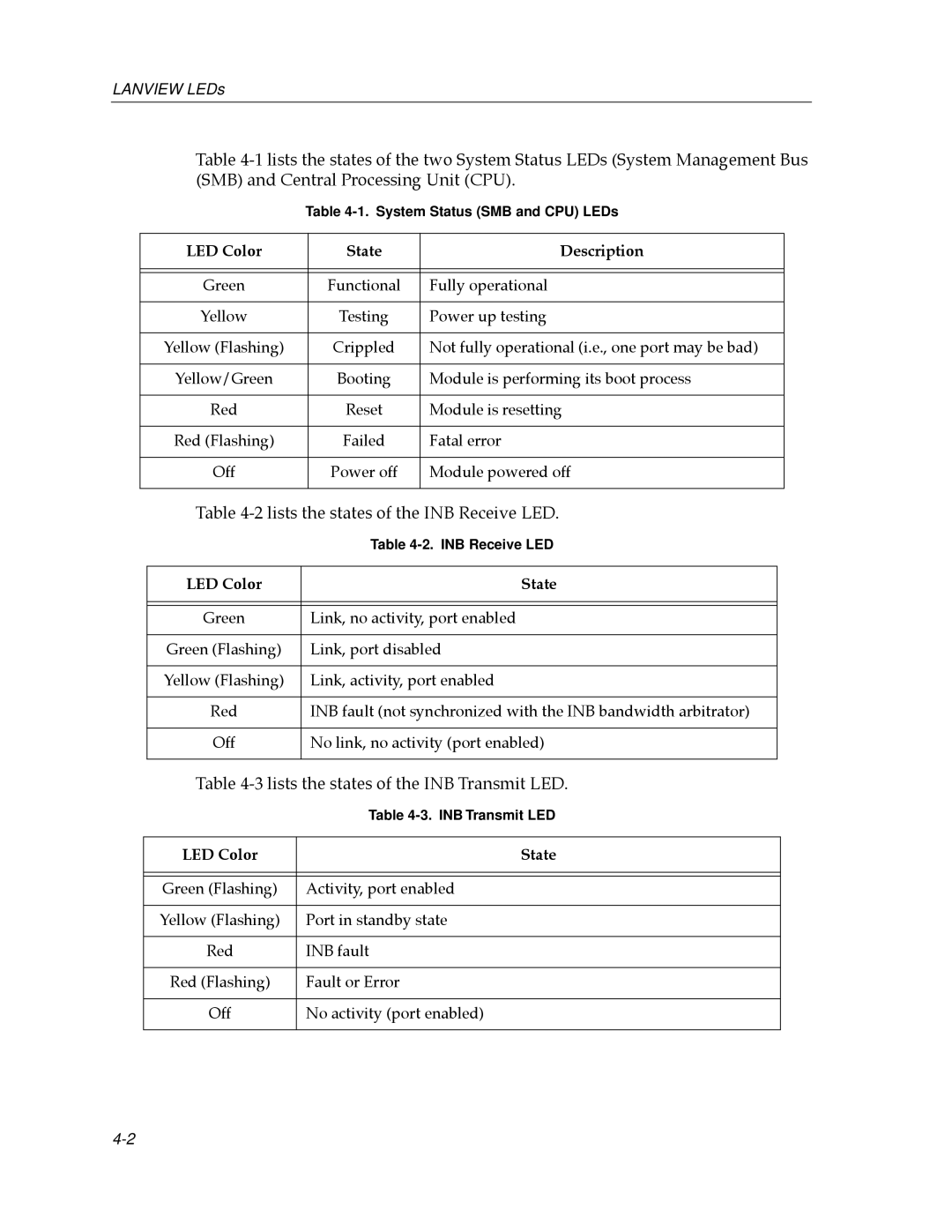
LED Color | State | Description |
|
|
|
|
|
|
Green | Functional | Fully operational |
|
|
|
Yellow | Testing | Power up testing |
|
|
|
Yellow (Flashing) | Crippled | Not fully operational (i.e., one port may be bad) |
|
|
|
Yellow/Green | Booting | Module is performing its boot process |
|
|
|
Red | Reset | Module is resetting |
|
|
|
Red (Flashing) | Failed | Fatal error |
|
|
|
Off | Power off | Module powered off |
|
|
|
Table 4-2 lists the states of the INB Receive LED.
| Table |
|
|
LED Color | State |
|
|
|
|
Green | Link, no activity, port enabled |
|
|
Green (Flashing) | Link, port disabled |
|
|
Yellow (Flashing) | Link, activity, port enabled |
|
|
Red | INB fault (not synchronized with the INB bandwidth arbitrator) |
|
|
Off | No link, no activity (port enabled) |
|
|
Table 4-3 lists the states of the INB Transmit LED.
| Table |
|
|
LED Color | State |
|
|
|
|
Green (Flashing) | Activity, port enabled |
|
|
Yellow (Flashing) | Port in standby state |
|
|
Red | INB fault |
|
|
Red (Flashing) | Fault or Error |
|
|
Off | No activity (port enabled) |
|
|