Operating Instructions and Parts Manual | AL2810 |
|
|
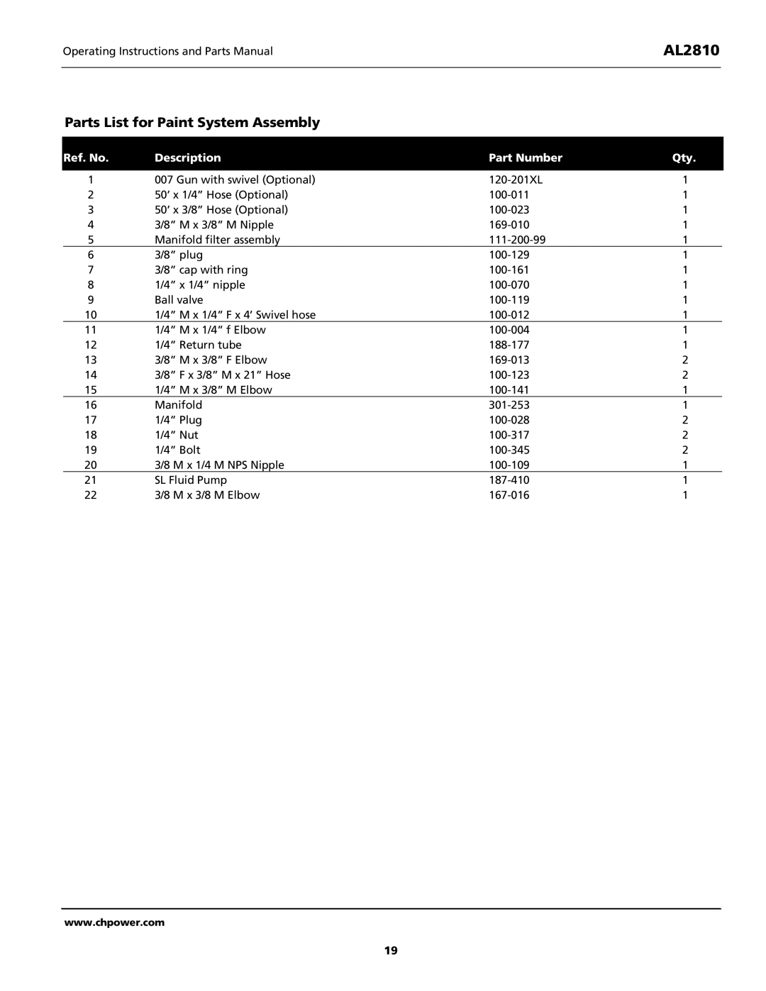
Parts List for Paint System Assembly
Ref. No. | Description | Part Number | Qty. | |
|
|
|
|
|
1 | 007 Gun with swivel (Optional) | 1 |
| |
2 | 50’ x 1/4” Hose (Optional) | 1 |
| |
3 | 50’ x 3/8” Hose (Optional) | 1 |
| |
4 | 3/8” M x 3/8” M Nipple | 1 |
| |
5 | Manifold filter assembly | 1 |
| |
6 | 3/8” plug | 1 |
| |
7 | 3/8” cap with ring | 1 |
| |
8 | 1/4” x 1/4” nipple | 1 |
| |
9 | Ball valve | 1 |
| |
10 | 1/4” M x 1/4” F x 4’ Swivel hose | 1 |
| |
11 | 1/4” M x 1/4” f Elbow | 1 |
| |
12 | 1/4” Return tube | 1 |
| |
13 | 3/8” M x 3/8” F Elbow | 2 |
| |
14 | 3/8” F x 3/8” M x 21” Hose | 2 |
| |
15 | 1/4” M x 3/8” M Elbow | 1 |
| |
16 | Manifold | 1 |
| |
17 | 1/4” Plug | 2 |
| |
18 | 1/4” Nut | 2 |
| |
19 | 1/4” Bolt | 2 |
| |
20 | 3/8 M x 1/4 M NPS Nipple | 1 |
| |
21 | SL Fluid Pump | 1 |
| |
22 | 3/8 M x 3/8 M Elbow | 1 |
| |
www.chpower.com
19
