internos de la herramienta.
3. Después de agre- gar aceite, haga funcionar la her- ramienta breve-
mente. Limpie todo exceso de aceite que salga del escape de la tapa.
CONEXION RECOMENDADA
La ilustración de abajo le muestra la conexión recomendada para la her- ramienta.
1. El compresor de aire debe tener la capaci- dad de suminis- trar un mínimo
de 4,14 bar cuando la herramienta esté en uso. Si el suministro de aire es inadecuado podría haber pérdida de potencia y falta de consistencia en el funcionamiento.
2. Puede utilizar un  lubricador para


 lubricar la her-

 ramienta.

 Igualmente, puede
  utilizar un filtro para remover las impurezas líquidas y sólidas que podrían oxidar u obstruir las partes internas de la herramienta.
3.Use siempre mangueras de suministro de aire, con una presión mínima de funcionamiento con clasificación igual o mayor que la presión de la fuente de energía si falla un regulador, o 10,34 bar, lo que sea mayor. Use mangueras de aire de 9,5 mm (3/8") para distancias de hasta 15 m (50’) ó más. Para un mejor rendimiento, instálele a la herramienta un conector rápido de 9,5mm (3/8”) (con roscas de 6,4mm (1/4”) NPT)
4.Use un regulador de presión (de 0 bar - 8,62 bar) en el compresor. Se necesita un regulador de presión para controlar la presión de operación de la herramienta entre 4,14 bar y 7,58 bar.
MODO DE OPERACIÓN
!ADVERTENCIA Siemprecer-
ciórese de saber en qué modo va a operar la herramienta antes de comen- zar a usarla. De lo contrario, le podría ocasionar la muerte o heridas graves.
MODO DE SECUENCIA ÚNICA
Este sistema requiere que oprima el gatillo cada vez que
vaya a clavar un sujetador. Para clavar, el elemento de contacto debe tocar la superficie de trabajo y el operador debe oprimir el gatillo.
Debe soltar el gatillo antes de clavar otro sujetador.
CÓMO USAR LA HERRAMIENTA DE DISPARO SECUENCIAL
!PRECAUCION Chequeeel
funcionamiento del mecanismo del elemento de contacto antes de cada uso. El elemento de contacto se debe desplazar libremente, sin pegarse, a lo largo del área de desplazamiento. El resorte del elemento de contacto debe regresar el elemento de contacto a su posición original totalmente extendido. No use la herramienta si el mecanismo del elemento de contacto no está fun- cionando adecudamente. Podría oca- sionarle heridas.
1. Desconecte la herramienta de la fuente de suministro de aire.
ambos sentidos sin atascarse o pegarse.
4.Reconecte la her- ramienta a la
fuente de sumin- istro de aire.
5.Presione el Elemento de Contacto de Trabajo contra la superficie de traba-
jo sin apretar el gatillo. La her- ramienta NO DEBE OPERAR. No use la herramienta si opera sin apre- tar el gatillo. Se pueden producir lesiones personales.
6.Remueva la her- ramienta de la super- ficie de trabajo. El Elemento de
Contacto de Trabajo  tiene que volver a su posición origi- nal. La herramienta NO DEBE OPERAR. No use la herramienta si opera mientras está levantada de la superficie de trabajo.
7.Apriete el gatillo y pre-
Contacto de Trabajo contra la superficie de trabajo. La herramien- ta NO DEBE hacerse funcionar.
8.Presione el Elemento de
Contacto de | | |
Trabajo con- | 1 | 2 |
tra la superficie de trabajo. Apriete el gatillo. La herramienta DEBE OPERAR.
!ADVERTENCIA Una
herramienta que funciona de manera inadecuada no debe usarse. No active la herramienta a menos que esté
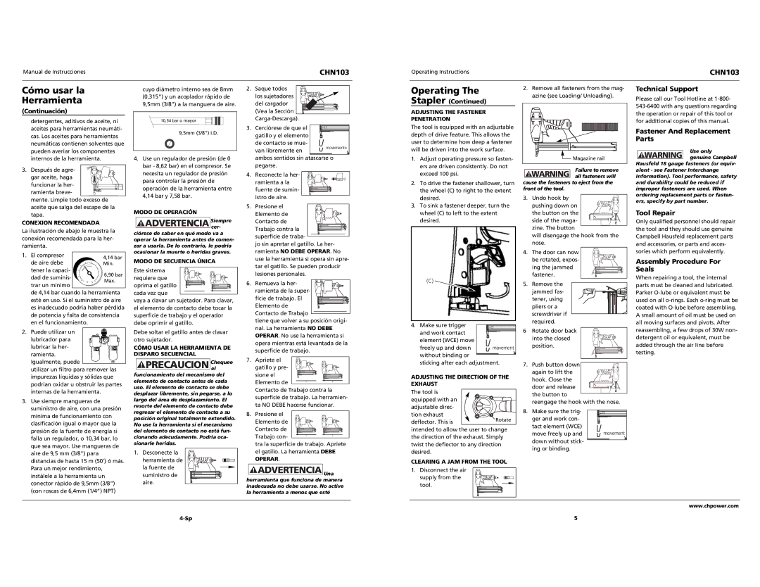
1.Adjust operating pressure so fasten- ers are driven consistently. Do not exceed 100 psi.
2.To drive the fastener shallower, turn the wheel (C) to right to the extent desired.
3.To sink a fastener deeper, turn the wheel (C) to left to the extent desired.
(C) 
4.Make sure trigger and work contact
element (WCE) move
freely up and down movement without binding or
sticking after each adjustment.
ADJUSTING THE DIRECTION OF THE EXHAUST
The tool is equipped with an adjustable direc-
tion exhaust
deflector. This isRotate intended to allow the user to change the direction of the exhaust. Simply twist the deflector to any direction desired.
CLEARING A JAM FROM THE TOOL
1. Disconnect the air supply from the tool.
Failure to remove
! WARNING all fasteners will cause the fasteners to eject from the front of the tool.
3.Undo hook by pushing down on
the button on the side of the maga-
zine. The button
will disengage the hook from the nose.
4.The door can now be rotated, expos- ing the jammed fastener.
5.Remove the
jammed fas- tener, using pliers or a screwdriver if required.
6Rotate door back into the closed position.
7.Push button down  again to lift the
hook. Close the door and release the button to
reengage the hook with the nose.
8. Make sure the trig- | |
ger and work con- | |
tact element (WCE) | |
move freely up and | movement |
down without stick- | |
ing or binding. | |
genuine Campbell Hausfeld 18 gauge fasteners (or equiv- alent - see Fastener Interchange Information). Tool performance, safety and durability could be reduced if improper fasteners are used. When ordering replacement parts or fasten- ers, specify by part number.
Tool Repair
Only qualified personnel should repair the tool and they should use genuine Campbell Hausfeld replacement parts and accessories, or parts and acces- sories which perform equivalently.
Assembly Procedure For Seals
When repairing a tool, the internal parts must be cleaned and lubricated. Parker O-lube or equivalent must be used on all o-rings. Each o-ring must be coated with O-lube before assembling. A small amount of oil must be used on all moving surfaces and pivots. After reassembling, a few drops of 30W non- detergent oil or equivalent, must be added through the air line before testing.