Operating Instructions
GTAW Arc Welding Torch
voltage and amperage. Follow the specifications on the welder front panel.
●The receptacle used for the welder must be properly grounded and the welder must be the only load on the power supply circuit.
The Components of TIG Welding (not included with your WT6100 TIG torch) are:
1.A constant current power supply such as the Arcitech 110 inverter technology arc welder.
2.A bottle of 100% Argon Shielding gas
3.An Argon regulator with proper connections from the regulator to the TIG torch.
4.Filler metal
5.Proper safety equipment such as a welding helmet and gloves.
Set Up:
Torch connection to power supply - The WT6100 torch comes with a quick connect Dinse plug that is plugged in to the NEGATIVE
The Work clamp is plugged in to the POSITIVE (+) receptacle of the power supply.
A beginning heat output amp setting is selected based on the thickness of the steel to be welded (See chart below).
100% Argon shielding gas is connected to the torch at a regulated rate of 15 - 30 cubic feet per hour (cfh.) If you have too little gas, you will see porosity of your weld. Too much flow is just a waste of gas.
Filler metal is applied to the TIG weld by hand feeding as is done with oxy- acetylene (flame power) welding. The filler metal must match the material you are welding. For welding mild steel, use an
Tungsten Electrodes come in a variety of compositions and sizes. Since the Arcitech 110 welder with WT6100 torch is a DC TIG welder, you should use only 2% Thoriated tungsten electrodes. These electrodes have a red identification mark. The diameter of the electrode is determined by the thickness of the material being welded. (See chart).
THE COLLET AND COLLET BODY SIZE MUST MATCH THE DIAMETER OF THE TUNGSTEN ELECTRODE.
Before installing the Tungsten Electrode you must grind a point on the welding end of the electrode. A point of 15 - 30 degrees is desired. It is important to grind the point with grinding marks running lengthwise as opposed to running the direction of the diameter.
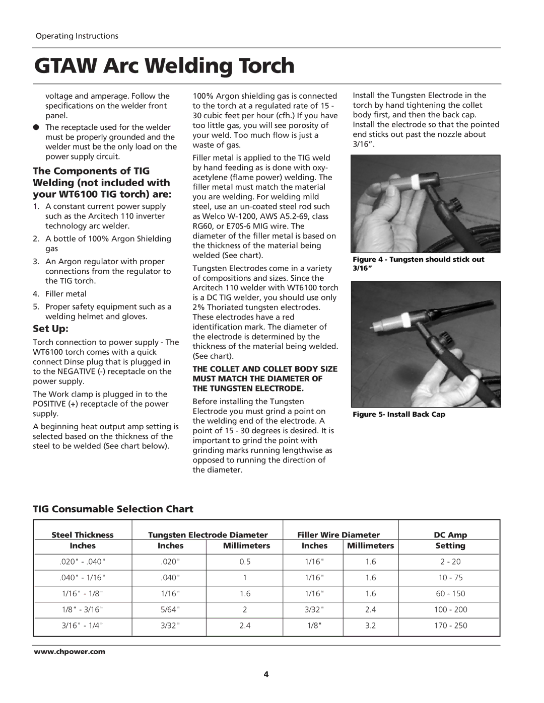
Install the Tungsten Electrode in the torch by hand tightening the collet body first, and then the back cap.
Install the electrode so that the pointed end sticks out past the nozzle about 3/16”.
Figure 4 - Tungsten should stick out 3/16”
Figure 5- Install Back Cap
TIG Consumable Selection Chart
|
| Steel Thickness | Tungsten Electrode Diameter | Filler Wire Diameter | DC Amp |
| |||
|
| Inches | Inches | Millimeters | Inches | Millimeters | Setting |
| |
|
|
|
|
|
|
|
|
| |
|
| .020" | .020" | 0.5 | 1/16" | 1.6 | 2 - 20 |
| |
|
|
|
|
|
|
|
|
|
|
|
| .040" - 1/16" | .040" | 1 | 1/16" | 1.6 | 10 | - 75 |
|
|
|
|
|
|
|
|
|
| |
|
| 1/16" - 1/8" | 1/16" | 1.6 | 1/16" | 1.6 | 60 - 150 |
| |
|
|
|
|
|
|
|
|
|
|
|
| 1/8" - 3/16" | 5/64" | 2 | 3/32" | 2.4 | 100 | - 200 |
|
|
|
|
|
|
|
|
|
|
|
|
| 3/16" - 1/4" | 3/32" | 2.4 | 1/8" | 3.2 | 170 | - 250 |
|
|
|
|
|
|
|
|
|
|
|
|
|
|
|
|
|
|
|
|
|
www.chpower.com
4