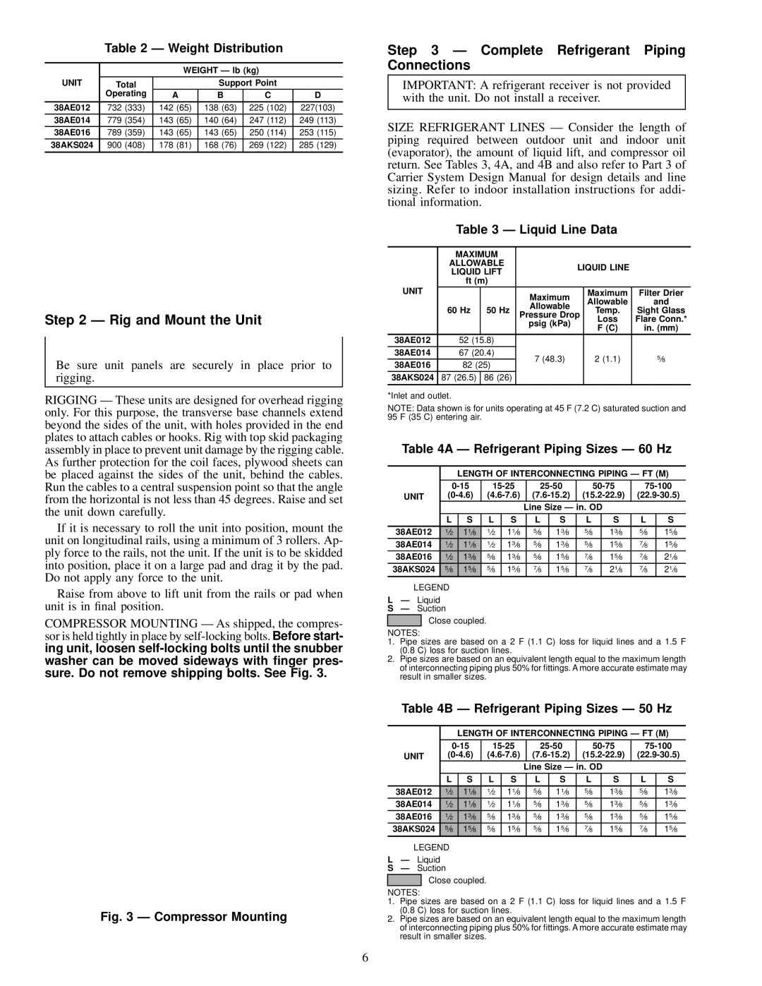
38AE014, 38AE016, 38AE012 specifications
The Carrier 38AE012, 38AE016, and 38AE014 are part of the Carrier series of packaged rooftop air conditioning units, designed to deliver reliable and efficient cooling solutions for commercial and industrial applications. These units showcase advanced engineering and technology, addressing the diverse needs of modern HVAC systems.One of the primary features of the Carrier 38AE series is their high-efficiency performance. They utilize advanced scroll compressor technology, which results in lower energy consumption while providing consistent cooling. With high SEER (Seasonal Energy Efficiency Ratio) ratings, these units help businesses reduce operational costs while maintaining comfortable indoor environments.
The construction of the Carrier 38AE units emphasizes durability and resilience. Built with high-quality materials, they are engineered to withstand harsh weather conditions and the rigors of daily use. The weatherized cabinets protect internal components from precipitation and corrosion, ensuring long-term reliability.
The 38AE series incorporates a sophisticated electronic control system that enhances performance monitoring and diagnostics. This feature allows facility managers to easily manage and optimize the unit's operations, improving efficiency and reducing potential downtime. Integrated with smart controls, these systems can be programmed for specific operating schedules, allowing for further energy savings.
Another standout technology in the Carrier 38AE series is the environmentally friendly refrigerant. By utilizing R-410A, these units contribute to reduced ozone depletion while still providing powerful cooling capabilities. This aligns with contemporary regulatory standards and climate initiatives to promote sustainable usage of HVAC systems.
The Carrier 38AE012, 38AE016, and 38AE014 models also excel in noise reduction technology, which is essential for commercial settings where ambient noise levels need to be minimized. The design includes low-noise fans and strategically placed insulation, resulting in quieter operation that enhances comfort for occupants.
In terms of installation, these units are versatile and can be easily mounted on building rooftops or on the ground. They feature a compact design, which facilitates seamless integration into existing structures without requiring extensive modifications.
Overall, the Carrier 38AE012, 38AE016, and 38AE014 models stand out for their combination of efficiency, durability, and advanced technology. They cater to a wide range of commercial needs, providing essential cooling while prioritizing sustainability and user comfort. With a commitment to innovation, Carrier continues to be a leader in the HVAC industry, ensuring that their products meet the evolving demands of energy efficiency and reliability.

