38AK012, 38AKS009, 38AKS012, 38AKS008, 38AK008 specifications
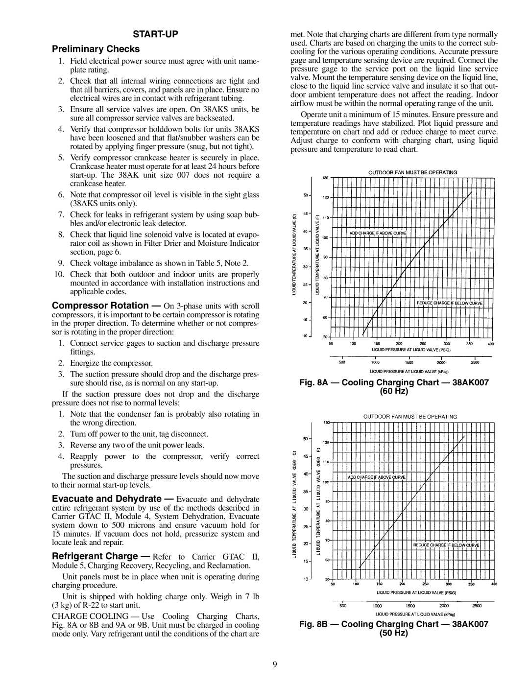
The Carrier 38AK007 is a state-of-the-art air conditioning system designed for optimal comfort, efficiency, and reliability, making it a standout choice for residential and commercial applications. This model exemplifies Carrier's commitment to innovation and energy efficiency, catering to diverse cooling needs.One of the key features of the Carrier 38AK007 is its high energy efficiency ratio (EER), which ensures lower energy consumption and reduced utility bills. With advanced inverter technology, this unit adjusts its cooling output based on the current requirements, thereby minimizing energy waste. This makes it an environmentally friendly option, contributing to lower greenhouse gas emissions while providing effective cooling.
The Carrier 38AK007 is also equipped with a variable-speed compressor, which enhances its performance and reliability. The compressor operates at different speeds, allowing the system to maintain a consistent room temperature without the peaks and valleys associated with traditional systems. This ensures not only increased comfort but also quieter operation, making it ideal for homes, offices, and other noise-sensitive environments.
In terms of technological innovation, the Carrier 38AK007 features Smart Thermostat compatibility, allowing users to control their cooling settings remotely via a smartphone or tablet. This integration with smart home systems provides users with added convenience, enabling them to adjust temperature settings from anywhere, ensuring optimal comfort even before arriving home.
The model is built with a robust and durable construction, featuring weather-resistant materials that withstand various environmental conditions. This durability ensures a long lifespan, reducing the frequency and costs of maintenance. Additionally, the Carrier 38AK007 includes a multi-stage filtration system that effectively captures allergens and pollutants from the indoor air, improving overall air quality.
Overall, the Carrier 38AK007 is designed to meet the modern demands for energy efficiency, user control, and durability. Its combination of advanced technologies, such as inverter technology and smart home compatibility, along with high performance and air quality features, makes it an excellent choice for anyone looking to invest in a reliable cooling solution. Whether for a residential setting or a commercial space, the Carrier 38AK007 stands out as a leader in the air conditioning market.

