Fig. 4 — Typical Compressor Mounting

(38AKS Units)

FILTER DRIER AND MOISTURE INDICATOR — The fil- ter drier is factory installed. Moisture indicator is field-supplied and should be installed just after liquid line shutoff valve. Do not use a receiver; there is none provided with unit and one should not be used.

NOTE: Unit is shipped with R-22 holding charge. System pressure must be relieved before removing caps. Recover refrigerant prior to brazing.

Pass nitrogen or other inert gas through piping while braz- ing to prevent formation of copper oxide.

Install field-supplied thermostatic expansion valve to evap- orator section. It is recommended that a field-supplied liquid line solenoid be positioned in the main liquid line close to the evaporator coil, and wired to close when compressor stops to minimize refrigerant migration during the ‘‘OFF’’ cycle.

Table 4A — Liquid Line Data — 60 Hz


MAX


LIQUID LINE


UNIT

ALLOWABLE

Max Allowable

Max Allowable

38


LIQUID LIFT

Pressure Drop

Temp Loss


Ft


M

psi

kPa

F

C

AK007

86


26.2

7

48.3

2

1

AK008

60


18.3

7

48.3

2

1

AK012

70


21.3

7

48.3

2

1

AKS008

60


18.3

7

48.3

2

1

AKS009

65


19.8

7

48.3

2

1

AKS012

65


19.8

7

48.3

2

1

NOTE: Values shown are for units operating at 45 F (7.2 C) satu- rated suction and 95 F (35 C) entering air.

Table 4B — Liquid Line Data — 50 Hz


MAX


LIQUID LINE


UNIT

ALLOWABLE

Max Allowable

Max Allowable

38

LIQUID LIFT

Pressure Drop

Temp Loss


Ft


M

psi

kPa

F

C

AK007

76


23.2

7

48.3

2

1

AK008

50


15.2

7

48.3

2

1

AK012

57


17.4

7

48.3

2

1

AKS008

50


15.2

7

48.3

2

1

AKS009

52


15.8

7

48.3

2

1

AKS012

52


15.8

7

48.3

2

1

NOTE: Values shown are for units operating at 45 F (7.2 C) satu- rated suction and 95 F (35 C) entering air.

Step 4 — Make Electrical Connections

Unit cabinet must have an uninterrupted, unbroken electri- cal ground to minimize the possibility of personal injury if an electrical fault should occur. This ground may consist of electrical wire connected to unit ground lug in control com- partment, or conduit approved for electrical ground when installed in accordance with NEC ANSI (American National Standards Institute)/NFPA (National Fire Protec- tion Association) 70 (U.S.A. Standards) and local electrical codes. Failure to follow this warning could result in the installer being liable for personal injury of others.

FIELD POWER SUPPLY — All units except 208/230-v units are factory wired for the voltage shown on the nameplate. If the 208/230-v unit is to be connected to a 208-v power supply, the transformer must be rewired by moving the black wire from the 230-v 1/4-in. spade terminal on the transformer and connecting it to the 200-v 1/4-in. spade terminal from the transformer.

Refer to unit label diagram for additional information. Pigtails are provided for field wire connections. Use factory- supplied splices or UL (Underwriters’ Laboratories) (U.S.A. Standard) approved copper/aluminum connector.

When installing units, provide a disconnect per NEC. All field wiring must comply with NEC and local requirements.

Install field wiring as follows:

1.Install conduit through side panel openings.

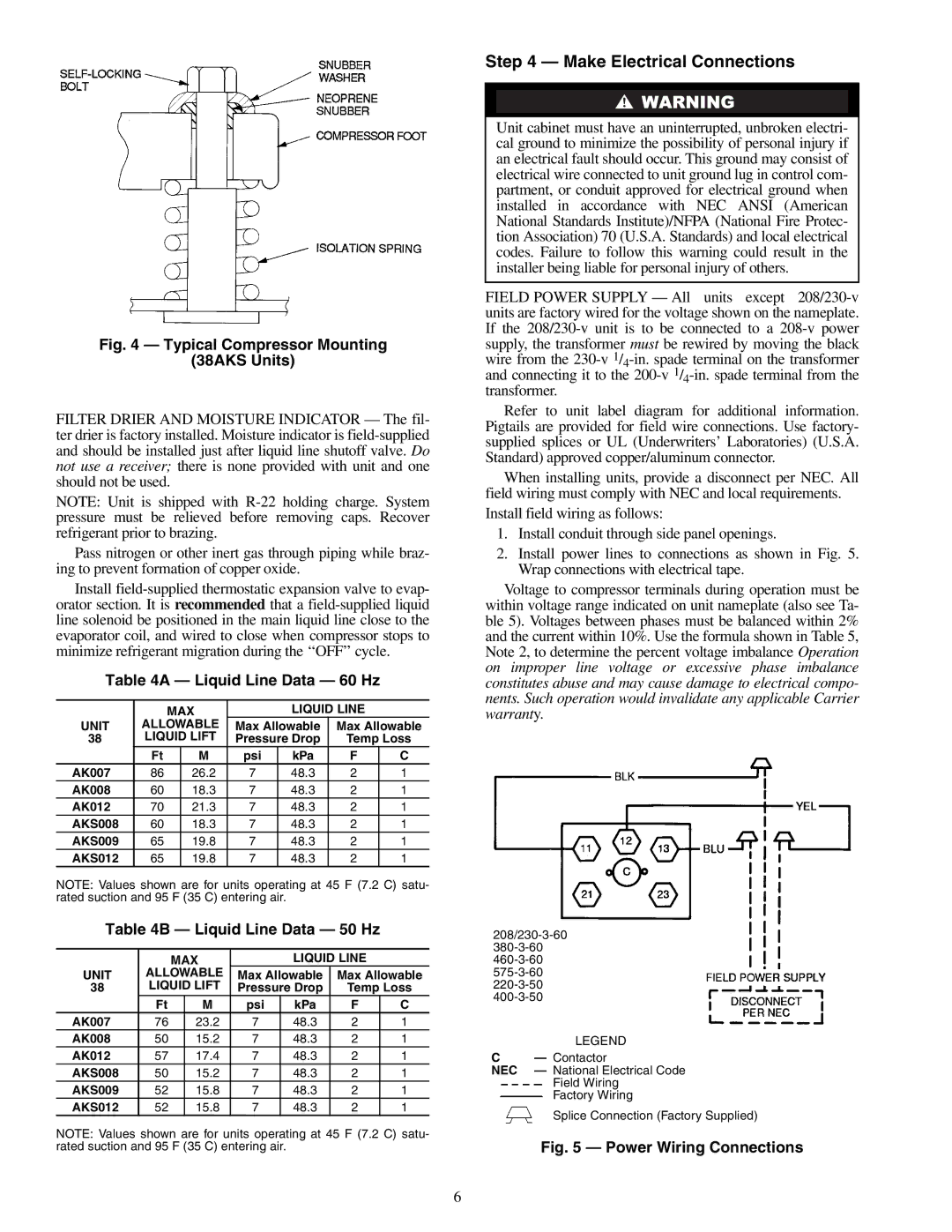
2.Install power lines to connections as shown in Fig. 5. Wrap connections with electrical tape.

Voltage to compressor terminals during operation must be within voltage range indicated on unit nameplate (also see Ta- ble 5). Voltages between phases must be balanced within 2% and the current within 10%. Use the formula shown in Table 5, Note 2, to determine the percent voltage imbalance Operation on improper line voltage or excessive phase imbalance constitutes abuse and may cause damage to electrical compo- nents. Such operation would invalidate any applicable Carrier warranty.

208/230-3-60 380-3-60 460-3-60 575-3-60 220-3-50 400-3-50

LEGEND

CContactor

NEC — National Electrical Code

Field Wiring

Factory Wiring

Splice Connection (Factory Supplied)

Fig. 5 — Power Wiring Connections

6

Page 6
Image 6
Carrier 38AK007, 38AKS012, 38AK008 Make Electrical Connections, Liquid Line Data 60 Hz, Liquid Line Data 50 Hz, Liquid Lift

38AK012, 38AKS009, 38AKS012, 38AKS008, 38AK008 specifications

The Carrier 38AK007 is a state-of-the-art air conditioning system designed for optimal comfort, efficiency, and reliability, making it a standout choice for residential and commercial applications. This model exemplifies Carrier's commitment to innovation and energy efficiency, catering to diverse cooling needs.

One of the key features of the Carrier 38AK007 is its high energy efficiency ratio (EER), which ensures lower energy consumption and reduced utility bills. With advanced inverter technology, this unit adjusts its cooling output based on the current requirements, thereby minimizing energy waste. This makes it an environmentally friendly option, contributing to lower greenhouse gas emissions while providing effective cooling.

The Carrier 38AK007 is also equipped with a variable-speed compressor, which enhances its performance and reliability. The compressor operates at different speeds, allowing the system to maintain a consistent room temperature without the peaks and valleys associated with traditional systems. This ensures not only increased comfort but also quieter operation, making it ideal for homes, offices, and other noise-sensitive environments.

In terms of technological innovation, the Carrier 38AK007 features Smart Thermostat compatibility, allowing users to control their cooling settings remotely via a smartphone or tablet. This integration with smart home systems provides users with added convenience, enabling them to adjust temperature settings from anywhere, ensuring optimal comfort even before arriving home.

The model is built with a robust and durable construction, featuring weather-resistant materials that withstand various environmental conditions. This durability ensures a long lifespan, reducing the frequency and costs of maintenance. Additionally, the Carrier 38AK007 includes a multi-stage filtration system that effectively captures allergens and pollutants from the indoor air, improving overall air quality.

Overall, the Carrier 38AK007 is designed to meet the modern demands for energy efficiency, user control, and durability. Its combination of advanced technologies, such as inverter technology and smart home compatibility, along with high performance and air quality features, makes it an excellent choice for anyone looking to invest in a reliable cooling solution. Whether for a residential setting or a commercial space, the Carrier 38AK007 stands out as a leader in the air conditioning market.