2

UNIT MODELS

CHASSIS


UNIT SIZE

M


OPERATING WT

38HDF

38HDR

SIZE

A

B

C

D

E

F

G

H

J

K

L

N

P

in.

mm

lb

kg


Unit Size

Unit Size

(Reference)

2′-11/8

3′-015/16 1′-29/16

1′-4″

1′-117/16

1′-53/16 1′-51/8

1′-10″

1′-1″

0′-65/8

0′-111/4 0′-215/16

0′-6″


018

5/8

15.88

166

75.3


018

018

0


024

5/8

15.88

176

79.8

(638.2)

(938.2)

(369.9)

(406.4)

(595.3)

(436.6)

(435)

(559.1)

(330.2)

(168.3)

(285.8)

(75)

(152.4)

38HDF


2′-71/8

3′-015/16

1′-29/16

1′-4″

1′-117/16

1′-53/16

1′-111/8

2′-4″

1′-2″

0′-63/4

0′-115/8

0′-215/16

0′-6″

030

3/4

19.05

187

84.8

024,030

024

0.6


(790.6)

(938.2)

(369.9)

(406.4)

(595.3)

(436.6)

(587.4)

(711.5)

(355.6)

(171.5)

(295.3)

(75)

(152.4)


036

3/4

19.05

250

113.4


036

030,036

1.0

3′-13/16

3′-89/16 1′-51/16

1′-67/16

2′-61/2

1′-75/8 2′-53/16

2′-101/16

1′-111/16 0′-81/8

1′-37/8 0′-37/16

0′-61/2


018

5/8

15.88

166

75.8


(944.6)

(1131.9)

(433.4)

(468.3)

(774.7)

(498.5)

(741)

(865.5)

(347.7)

(206.4)

(403.2)

(88)

(165.4)


024

5/8

15.88

176

79.8

048,060

1.6

3′-73/16

3′-89/16 1′-51/16

1′-67/16

2′-61/2

1′-75/8 2′-113/16

3′-41/16

1′-21/2 0′-81/2

1′-67/8 0′-37/16

0′-61/2


030

3/4

19.05

187

84.8

(1097)

(1131.9)

(433.4)

(468.3)

(774.7)

(498.5)

(893.4)

(1017.9)

(354.2)

(215.9)

(479.4)

(88)

(165.4)

38HDR

NOTE: Dimensions shown in feet-inches. Dimensions in ( ) are millimeters.


036

3/4

19.05

250

113.4


048

7/8

22.22

278

126.1


060

7/8

22.22

306

138.8


MINIMUM MOUNTING PAD


UNIT SIZE


DIMENSIONS


Support Feet


ft-in.


mm


CHASSIS SIZES 0 & .6

1′-11″ x 3′-6″

584.2 x 1066.8


CHASSIS SIZES 1 & 1.6

2′-0″ x 4′-2″

609.6 x 1270


NOTES:


1. Required clearances: with coil facing wall, allow 6 in. minimum clearance


on coil side and coil end, and 3 feet minimum clearance on compressor


end and fan side. With fan facing wall, allow 8 in. minimum clearance on


fan side and coil end, and 3 feet minimum clearance on compressor end


and coil side. With multi-unit application, arrange units so discharge of one


does not enter inlet of another.


2. Dimensions in parenthesis are in millimeters.


3.

Center of Gravity

.


(FIELD PROVIDED AND INSTALLED)

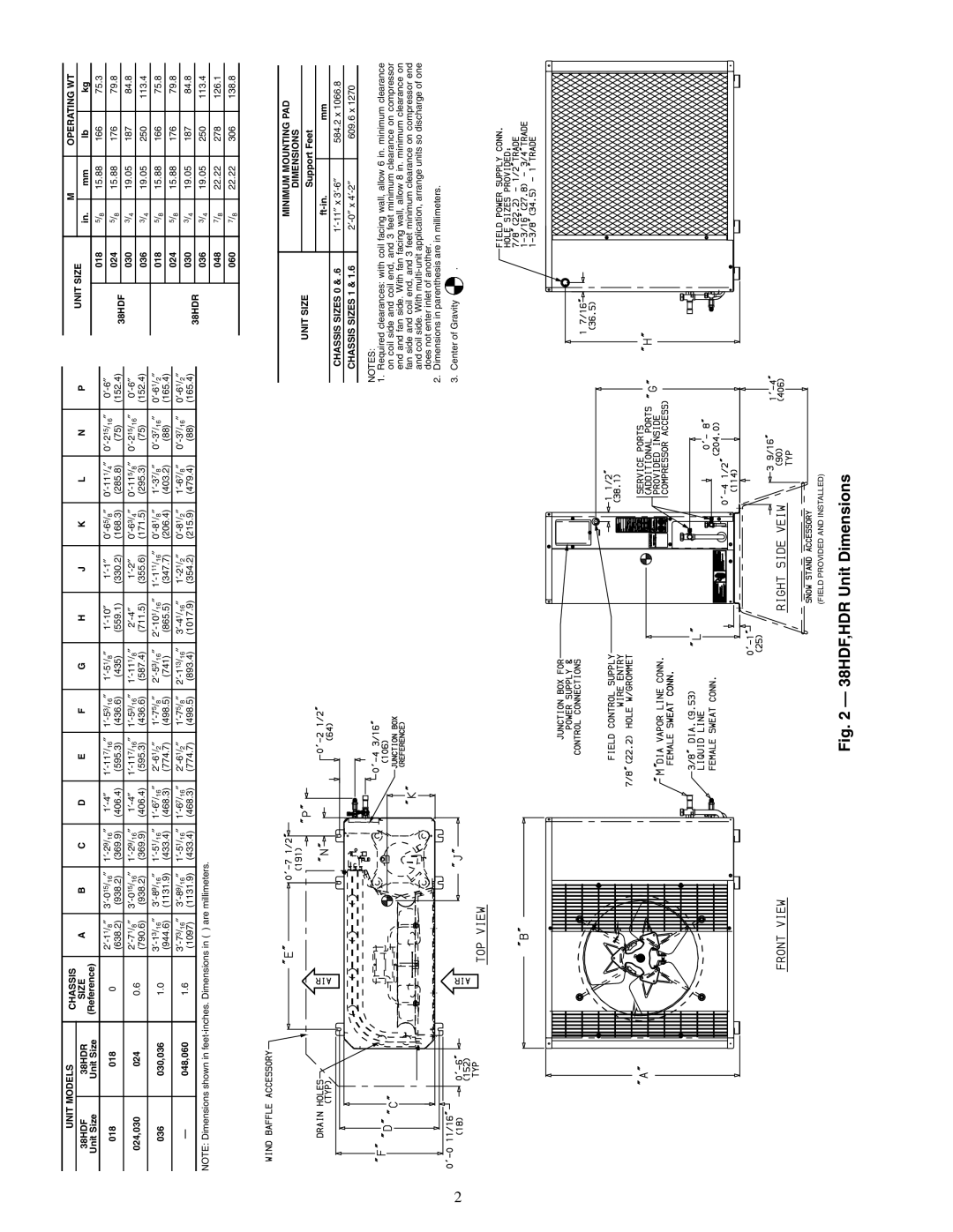
Fig. 2 — 38HDF,HDR Unit Dimensions

Page 2
Image 2
Carrier 38HDF018-036, 38HDR018-060 specifications 38HDF,HDR Unit Dimensions

38HDR018-060, 38HDF018-036 specifications

Carrier is a renowned name in HVAC technology, and their 38HDR018-060 and 38HDF018-036 models showcase the fine craftsmanship and innovation typical of the brand. These rooftop units are designed to deliver reliable heating and cooling solutions, making them an ideal choice for commercial spaces and industrial applications.

One of the main features of the Carrier 38HDR and 38HDF series is their ability to provide efficient climate control. The units are equipped with high-efficiency scroll compressors, which ensure reduced energy consumption while maintaining optimal performance. This efficiency translates into significant cost savings on energy bills, making these units an environmentally conscious choice as well.

In terms of design, the 38HDR and 38HDF models boast a rugged construction that can withstand various weather conditions. They are built with a galvanized steel cabinet that resists corrosion, ensuring durability and longevity. The compact design of these rooftop units allows for easy installation and integration into existing structures, offering flexibility for building owners and operators.

Advanced technology is at the heart of these Carrier units. The inclusion of a microprocessor-based control system enables precise temperature management and system monitoring. This technology not only optimizes performance but also provides valuable data for maintenance planning, ultimately reducing the risk of unexpected failures.

The units also come with variable air volume capabilities, which enhances comfort by allowing for customizable airflow to meet specific environmental needs. The 38HDR and 38HDF series is designed to be compatible with multiple zoning systems, allowing facilities to better adapt to changing occupancy and usage patterns.

With sound levels minimized through advanced acoustic engineering, these rooftop units operate quietly, ensuring minimal disruption to occupants. This is especially important in commercial settings, where a peaceful environment is crucial to productivity.

Moreover, both series support enhanced indoor air quality features. With the option for advanced filtration systems, they can effectively remove airborne contaminants, contributing to a healthier indoor environment.

In summary, Carrier's 38HDR018-060 and 38HDF018-036 rooftop units are a powerful combination of efficiency, durability, and advanced technology. Their ability to provide customized heating and cooling solutions makes them an excellent investment for any commercial or industrial application, ensuring comfort and performance for years to come.