Step 4 — Make Electrical Connections

Unit cabinet must have an uninterrupted, unbroken electri- cal ground to minimize the possibility of personal injury if an electrical fault should occur. This ground may consist of electrical wire connected to unit ground lug in control com- partment, or conduit approved for electrical ground when installed in accordance with NEC, and local electrical codes. Failure to follow this warning could result in the installer being liable for the personal injury of others.

Unit failure as a result of operation on improper line voltage or excessive phase imbalance constitutes abuse and may cause damage to electrical components. Such opera- tion would invalidate any applicable Carrier warranty.

Before performing service or maintenance, be sure indoor unit main power switch is turned OFF and indoor blower has stopped. Failure to do so may result in electrical shock or injury from rotating fan blades.

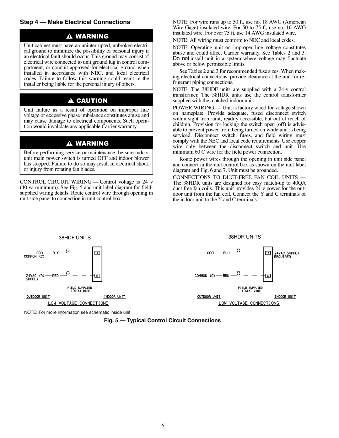
CONTROL CIRCUIT WIRING — Control voltage is 24 v (40 va minimum). See Fig. 5 and unit label diagram for field- supplied wiring details. Route control wire through opening in unit side panel to connection in unit control box.

NOTE: For wire runs up to 50 ft, use no. 18 AWG (American Wire Gage) insulated wire. For 50 to 75 ft, use no. 16 AWG insulated wire. For over 75 ft, use 14 AWG insulated wire.

NOTE: All wiring must conform to NEC and local codes.

NOTE: Operating unit on improper line voltage constitutes abuse and could affect Carrier warranty. See Tables 2 and 3. Do not install unit in a system where voltage may fluctuate above or below permissible limits.

See Tables 2 and 3 for recommended fuse sizes. When mak- ing electrical connections, provide clearance at the unit for re- frigerant piping connections.

NOTE: The 38HDF units are supplied with a 24-v control transformer. The 38HDR units use the control transformer supplied with the matched indoor unit.

POWER WIRING — Unit is factory wired for voltage shown on nameplate. Provide adequate, fused disconnect switch within sight from unit, readily accessible, but out of reach of children. Provision for locking the switch open (off) is advis- able to prevent power from being turned on while unit is being serviced. Disconnect switch, fuses, and field wiring must comply with the NEC and local code requirements. Use copper wire only between the disconnect switch and unit. Use minimum 60 C wire for the field power connection.

Route power wires through the opening in unit side panel and connect in the unit control box as shown on the unit label diagram and Fig. 6 and 7. Unit must be grounded.

CONNECTIONS TO DUCT-FREE FAN COIL UNITS — The 38HDR units are designed for easy match-up to 40QA duct free fan coils. This unit provides 24 v power for the out- door unit from the fan coil. Connect the Y and C terminals of the indoor unit to the Y and C terminals.

38HDF UNITS


38HDR UNITS


NOTE: For more information see schematic inside unit.

Fig. 5 — Typical Control Circuit Connections

6

Page 6
Image 6
Carrier 38HDF018-036, 38HDR018-060 specifications Make Electrical Connections, Typical Control Circuit Connections

38HDR018-060, 38HDF018-036 specifications

Carrier is a renowned name in HVAC technology, and their 38HDR018-060 and 38HDF018-036 models showcase the fine craftsmanship and innovation typical of the brand. These rooftop units are designed to deliver reliable heating and cooling solutions, making them an ideal choice for commercial spaces and industrial applications.

One of the main features of the Carrier 38HDR and 38HDF series is their ability to provide efficient climate control. The units are equipped with high-efficiency scroll compressors, which ensure reduced energy consumption while maintaining optimal performance. This efficiency translates into significant cost savings on energy bills, making these units an environmentally conscious choice as well.

In terms of design, the 38HDR and 38HDF models boast a rugged construction that can withstand various weather conditions. They are built with a galvanized steel cabinet that resists corrosion, ensuring durability and longevity. The compact design of these rooftop units allows for easy installation and integration into existing structures, offering flexibility for building owners and operators.

Advanced technology is at the heart of these Carrier units. The inclusion of a microprocessor-based control system enables precise temperature management and system monitoring. This technology not only optimizes performance but also provides valuable data for maintenance planning, ultimately reducing the risk of unexpected failures.

The units also come with variable air volume capabilities, which enhances comfort by allowing for customizable airflow to meet specific environmental needs. The 38HDR and 38HDF series is designed to be compatible with multiple zoning systems, allowing facilities to better adapt to changing occupancy and usage patterns.

With sound levels minimized through advanced acoustic engineering, these rooftop units operate quietly, ensuring minimal disruption to occupants. This is especially important in commercial settings, where a peaceful environment is crucial to productivity.

Moreover, both series support enhanced indoor air quality features. With the option for advanced filtration systems, they can effectively remove airborne contaminants, contributing to a healthier indoor environment.

In summary, Carrier's 38HDR018-060 and 38HDF018-036 rooftop units are a powerful combination of efficiency, durability, and advanced technology. Their ability to provide customized heating and cooling solutions makes them an excellent investment for any commercial or industrial application, ensuring comfort and performance for years to come.