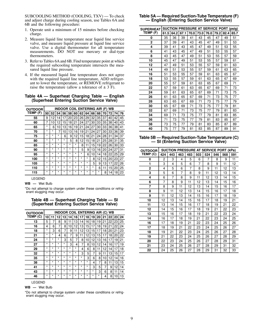
SUBCOOLING METHOD (COOLING, TXV) Ð To check and adjust charge during cooling season, use Tables 6A and

6B and the following procedure:

1.Operate unit a minimum of 15 minutes before checking charge.

2.Measure liquid line temperature near liquid line service valve, and measure liquid pressure at liquid line service valve. Use a digital thermometer for all temperature measurements. DO NOT use mercury or dial-type thermometers.

3.Refer to Tables 6A and 6B. Find temperature point at which the required subcooling temperature intersects the mea- sured liquid line pressure.

4.If the measured liquid line temperature does not agree with the required liquid line temperature, ADD refriger- ant to lower the temperature, or REMOVE refrigerant to raise the temperature (allow a tolerance of ± 3 F).

Table 4A Ð Superheat Charging Table Ð English

(Superheat Entering Suction Service Valve)

OUTDOOR


INDOOR COIL ENTERING AIR (F) WB


TEMP (F)

50

52


54

56

58

60

62

64

66

68

70

72


74

76

55

9

12


14

17

20

23

26

29

32

35

37

40


42

45

60

7

10


12

15

18

21

24

27

30

33

35

38


40

43

65

*

6


10

13

16

19

21

24

27

30

33

36


38

41

70

*

*


7

10

13

16

19

21

24

27

30

33


36

39

75

*

*


*

6

9

12

15

18

21

24

28

31


34

37

80

*

*


*

*

5

8

12

15

18

21

25

28


31

35

85

*

*


*

*

*

*

8

11

15

19

22

26


30

33

90

*

*


*

*

*

*

5

9

13

16

20

24


27

31

95

*

*


*

*

*

*

*

6

10

14

18

22


25

29

100

*

*


*

*

*

*

*

*

8

12

15

20


23

27

105

*

*


*

*

*

*

*

*

5

9

13

17


22

26

110

*

*


*

*

*

*

*

*

*

6

11

15


20

25

115

*

*


*

*

*

*

*

*

*

*

8

14


18

23


LEGEND

WB Ð Wet Bulb

*Do not attempt to charge system under these conditions or refrig- erant slugging may occur.

Table 4B Ð Superheat Charging Table Ð SI (Superheat Entering Suction Service Valve)

OUTDOOR


INDOOR COIL ENTERING AIR (C) WB


TEMP (C)

10

11

12

13

14

16

17

18

19

20

21

22


23

24

13

5

7


8

9

11

13

14

16

18

19

21

22


23

25

16

4

6


7

8

10

12

13

15

17

18

19

21


22

24

18

*

3


6

7

9

11

12

13

15

17

18

20


21

23

21

*

*


4

6

7

9

11

12

13

15

17

18


20

22

24

*

*


*

3

5

7

8

10

12

13

16

17


19

21

27

*

*


*

*

3

4

7

8

10

12

14

16


17

19

29

*

*


*

*

*

*

4

6

8

11

12

14


17

18

32

*

*


*

*

*

*

3

5

7

9

11

13


15

17

35

*

*


*

*

*

*

*

3

6

8

10

12


14

16

38

*

*

*

*

*

*

*

*

4

7

8

11

13

15

41

*

*

*

*

*

*

*

*

3

5

7

9


12

14

43

*

*

*

*

*

*

*

*

*

3

6

8


11

14

46

*

*

*

*

*

*

*

*

*

*

4

8


10

13


LEGEND

WB Ð Wet Bulb

*Do not attempt to charge system under these conditions or refrig- erant slugging may occur.

Table 5A Ð Required Suction-Tube Temperature (F)

Ð English (Entering Suction Service Valve)

SUPERHEAT

SUCTION PRESSURE AT SERVICE PORT (psig)

TEMP (F)

61.5

64.2

67.1

70.0

73.0

76.0

79.2

82.4

85.7

0

35

36

39

41

43

45

47

49

51

2

37

39

41

43

45

47

49

51

53

4

39

41

43

45

47

49

51

53

55

6

41

43

45

47

49

51

53

55

57

8

43

45

47

49

51

53

55

57

59

10

45

47

49

51

53

55

57

59

61

12

47

49

51

53

55

57

59

61

63

14

49

51

53

55

57

59

61

63

65

16

51

53

55

57

59

61

63

65

67

18

53

55

57

59

61

63

65

67

69

20

55

57

59

61

63

65

67

69

71

22

57

59

61

63

65

67

69

71

73

24

59

61

63

65

67

69

71

73

75

26

61

63

65

67

69

71

73

75

77

28

63

65

67

69

71

73

75

77

79

30

65

67

69

71

73

75

77

79

81

32

67

69

71

73

75

77

79

81

83

34

69

71

73

75

77

79

81

83

85

36

71

73

75

77

79

81

83

85

87

38

73

75

77

79

81

83

85

87

89

40

75

77

79

81

83

85

87

89

91


Table 5B Ð Required Suction-Tube Temperature (C)

Ð SI (Entering Suction Service Valve)

OUTDOOR

SUCTION PRESSURE AT SERVICE PORT (kPa)

TEMP (C)

424

443

463

483

503

524

546

568

591

0

2

3

4

5

6

7

8

9

11

1

3

4

5

6

7

8

9

11

12

2

4

5

6

7

8

9

11

12

13

3

5

6

7

8

9

11

12

13

14

4

6

7

8

9

11

12

13

14

15

6

7

8

9

11

12

13

14

15

16

7

8

9

11

12

13

14

15

16

17

8

9

11

12

13

14

15

16

17

18

9

11

12

13

14

15

16

17

18

19

10

12

13

14

15

16

17

18

19

21

11

13

14

15

16

17

18

19

21

22

12

14

15

16

17

18

19

21

22

23

13

15

16

17

18

19

21

22

23

24

14

16

17

18

19

21

22

23

24

25

16

17

18

19

21

22

23

24

25

26

17

18

19

21

22

23

24

25

26

27

18

19

21

22

23

24

25

26

27

28

19

21

22

23

24

25

26

27

28

29

20

22

23

24

25

26

27

28

29

31

21

23

24

25

26

27

28

29

31

32

22

24

25

26

27

28

29

31

32

33


9

Page 9
Image 9
Carrier 38HDL018-060 Outdoor Indoor Coil Entering AIR F WB Temp F, Outdoor Indoor Coil Entering AIR C WB Temp C, Superheat

38HDL018-060 specifications

The Carrier 38HDL018-060 is a prominent model in the world of commercial HVAC solutions, offering exceptional performance, efficiency, and reliability for a variety of applications, including offices, retail spaces, and industrial environments. With a range of capacities from 1.5 tons to 5 tons, the 38HDL series serves diverse heating and cooling needs, making it a versatile option for many building types.

One of the standout features of the Carrier 38HDL018-060 is its advanced Scroll compressor technology. This technology is known for its energy efficiency and quieter operation compared to traditional reciprocating compressors. By optimizing the refrigeration cycle, the Scroll compressor enhances the overall system performance, providing consistent temperature control while minimizing energy consumption.

The unit also incorporates a vertical air discharge design, allowing for flexible installation and improved airflow distribution. This design minimizes air stratification, ensuring that conditioned air reaches every corner of the space effectively. Furthermore, the 38HDL series is equipped with a reliable multi-speed fan that adapts its operation based on the specific cooling or heating demand, further optimizing energy use and maintaining indoor comfort levels.

In terms of technology, the Carrier 38HDL018-060 features a microprocessor-based control system. This intelligent control allows for precise temperature management and system diagnostics, enabling easier maintenance and ensuring the longevity of the unit. Additionally, the unit can be integrated with Carrier’s advanced building automation systems for streamlined control across larger facilities, further enhancing operational efficiency.

The 38HDL series is also designed with durability in mind. It features a rugged aluminum cabinet that stands up to harsh environmental conditions while providing excellent insulation to improve overall efficiency. The corrosion-resistant coatings contribute to the longevity of the finned coil and other critical components, ensuring reliable performance over time.

Overall, the Carrier 38HDL018-060 exemplifies modern HVAC technology, blending efficiency, durability, and advanced control features to create a solution that meets the demands of today’s commercial buildings. Whether for new construction or retrofitting an existing system, the 38HDL series offers the reliability and performance required to create a comfortable indoor environment.