38/40GXC(Q)

INSTALLATION GUIDE

Ideal installation locations include:

Indoor Unit

SA location where there are no obstacles near inlet and outlet area. S A location which can bear the weight of indoor unit.

S Do not install indoor units near a direct source of heat such as direct sunlight or a heating appliance.

S A location which provides appropriate clearances as outlined in Fig. 2 (pg. 5).

Outdoor Unit

S A location which is convenient to installation and not exposed to strong wind. If unit is exposed to strong winds it is recommended that a wind baffle be used. Contact your Carrier Representative for drawings. (See Fig. 11, pg. 7)

S A location which can bear the weight of outdoor unit and where the outdoor unit can be mounted in a level position.

S A location which provides appropriate clearances as outlined in Fig. 3 (pg. 5).

S Do not install the indoor or outdoor units in a location with special environmental conditions. For those applications, contact your Carrier Representative.

INDOOR UNIT INSTALLATION

INSTALL MOUNTING PLATE

1.Carefully remove the mounting plate, which is attached to the back of the indoor unit.

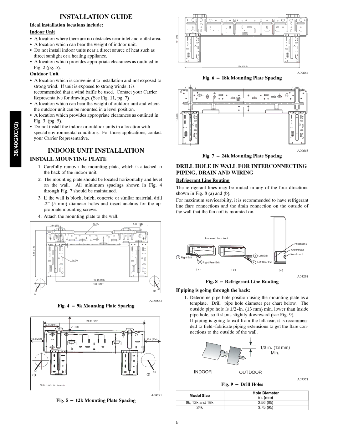
2.The mounting plate should be located horizontally and level on the wall. All minimum spacings shown in Fig. 4 through Fig. 7 should be maintained.

3.If the wall is block, brick, concrete or similar material, drill

.2” (5 mm) diameter holes and insert anchors for the ap- propriate mounting screws.

4.Attach the mounting plate to the wall.

2.64 (67)

.08 (2)

4.09 (104)


.52 (13)


8.58 (218)


.04 (1)


15.47 (393)


18.94 (481)


65


A085862

Fig. 4 ---9k Mounting Plate Spacing


21.93 (557)

3.15 (80)

7" (178)


10.4 (264)

10.4 (264)

65


Note: Units in ( ) = mm


A08291

Fig. 5 ---12k Mounting Plate Spacing

10.1 (256)

25.6 (650.5)

A09664

Fig. 6 ---18k Mounting Plate Spacing

11.4 (290)

A09665

Fig. 7 ---24k Mounting Plate Spacing

DRILL HOLE IN WALL FOR INTERCONNECTING PIPING, DRAIN AND WIRING

Refrigerant Line Routing

The refrigerant lines may be routed in any of the four directions shown in Fig. 8 (a) and (b).

For maximum serviceability, it is recommended to have refrigerant line flare connections and the drain connection on the outside of the wall that the fan coil is mounted on.

As viewed from front


Knockout 3


Knockout 2


3

Left Exit

Knockout 1

1 Right Exit


2 Right Rear Exit

4

Left Rear Exit


( a )

( b )


( c )

Fig. 8 ---


A08281

Refrigerant Line Routing


If piping is going through the back:

1.Determine pipe hole position using the mounting plate as a template. Drill pipe hole diameter per chart below. The outside pipe hole is 1/2-in. (13 mm) min. lower than inside pipe hole, so it slants slightly downward (see Fig. 9).

If piping is going to exit from the left rear, it is recommen- ded to field-fabricate piping extensions to get the flare con- nections to the outside of the wall.


1/2 in. (13 mm)


Min.

INDOOR

OUTDOOR


A07371


Fig. 9 ---Drill Holes

Model Size

Hole Diameter

in. (mm)


9k, 12k and 18k

2.56 (65)

24k

3.75 (95)

6

Page 6
Image 6
Carrier 38GXQ, 40GXQ, 40GXC, 38GXC Installation Guide, Indoor Unit Installation, Install Mounting Plate

38GXC, 38GXQ, 40GXC, 40GXQ specifications

Carrier's 40GXQ, 38GXQ, 38GXC, and 40GXC series are a testament to the brand’s commitment to innovation and excellence in HVAC technology. These units are designed to meet the diverse needs of commercial and residential applications while ensuring optimal performance, energy efficiency, and sustainability.

The 40GXQ model stands out for its advanced cooling capabilities and high efficiency. This rooftop unit employs a high-efficiency scroll compressor that enhances performance while minimizing energy consumption. With a cooling capacity ranging from 3 to 20 tons, the 40GXQ is ideal for larger spaces requiring significant cooling load management. It also features a user-friendly interface, allowing for easy adjustments and monitoring through a digital display.

The 38GXQ is particularly notable for its versatility and robust design. Featuring an integrated economizer, the 38GXQ allows for enhanced energy savings by leveraging outdoor air for free cooling when conditions permit. This model is equipped with high-efficiency filters that improve indoor air quality, making it suitable for applications in schools, offices, and healthcare facilities.

The 38GXC variant is designed for residential applications and emphasizes whisper-quiet operation without compromising performance. Its high SEER (Seasonal Energy Efficiency Ratio) rating means homeowners can enjoy substantial savings on their energy bills. The 38GXC is also equipped with Carrier's Greenspeed intelligence, which enables the system to modulate its output, maintaining comfort levels while reducing energy consumption.

The 40GXC model represents innovation in temperature control systems. With its sleek design and advanced variable-speed compressor, the 40GXC can adapt to changing conditions while maintaining efficiency and performance. This model also incorporates advanced monitoring systems that provide real-time data on performance and diagnostics, ensuring optimum efficiency throughout its lifecycle.

All these Carrier models are equipped with advanced refrigerant management systems, supporting environmentally friendly refrigerants that adhere to current environmental regulations. They not only provide effective cooling solutions but also contribute to a sustainable future, aligning with Carrier’s broader commitment to reducing carbon footprints.

In summary, the Carrier 40GXQ, 38GXQ, 38GXC, and 40GXC are engineered to deliver exceptional performance, energy efficiency, and versatility across various applications. With advanced technologies and a commitment to sustainability, these units set a high standard in the HVAC industry. Whether for commercial or residential use, these models provide reliable and efficient climate control solutions.