48EZ-A specifications
The Carrier 48EZ-A and 48VT-A are two advanced rooftop unit air conditioners that exemplify innovation and efficiency in HVAC technology. Designed for commercial applications, these units provide optimal comfort while ensuring energy conservation and reliability.One of the standout features of the Carrier 48EZ-A is its high-efficiency cooling system. With SEER ratings reaching up to 16, this model uses advanced compressor technology to ensure that energy consumption stays low while maximizing cooling output. The 48EZ-A incorporates a two-stage scroll compressor that enhances performance during partial load conditions, making it ideal for varying temperature demands throughout the day.
Meanwhile, the Carrier 48VT-A is designed with variable speed technology that allows for precise modulation of airflow and cooling capacity, adapting seamlessly to real-time building conditions. This technology not only improves comfort but also significantly reduces energy usage by optimizing operational efficiency.
Both units are equipped with advanced microprocessor controls that facilitate superior management of the HVAC system. The controls offer programmable options allowing for enhanced control over system operation, scheduling, and diagnostics. This promotes easy maintenance and ensures long-term reliability.
In terms of construction, the Carrier 48EZ-A and 48VT-A units are built with corrosion-resistant materials, ensuring durability and longevity even in challenging environments. The cabinet is designed with insulated panels to minimize sound levels, making them suitable for installation in noise-sensitive locations.
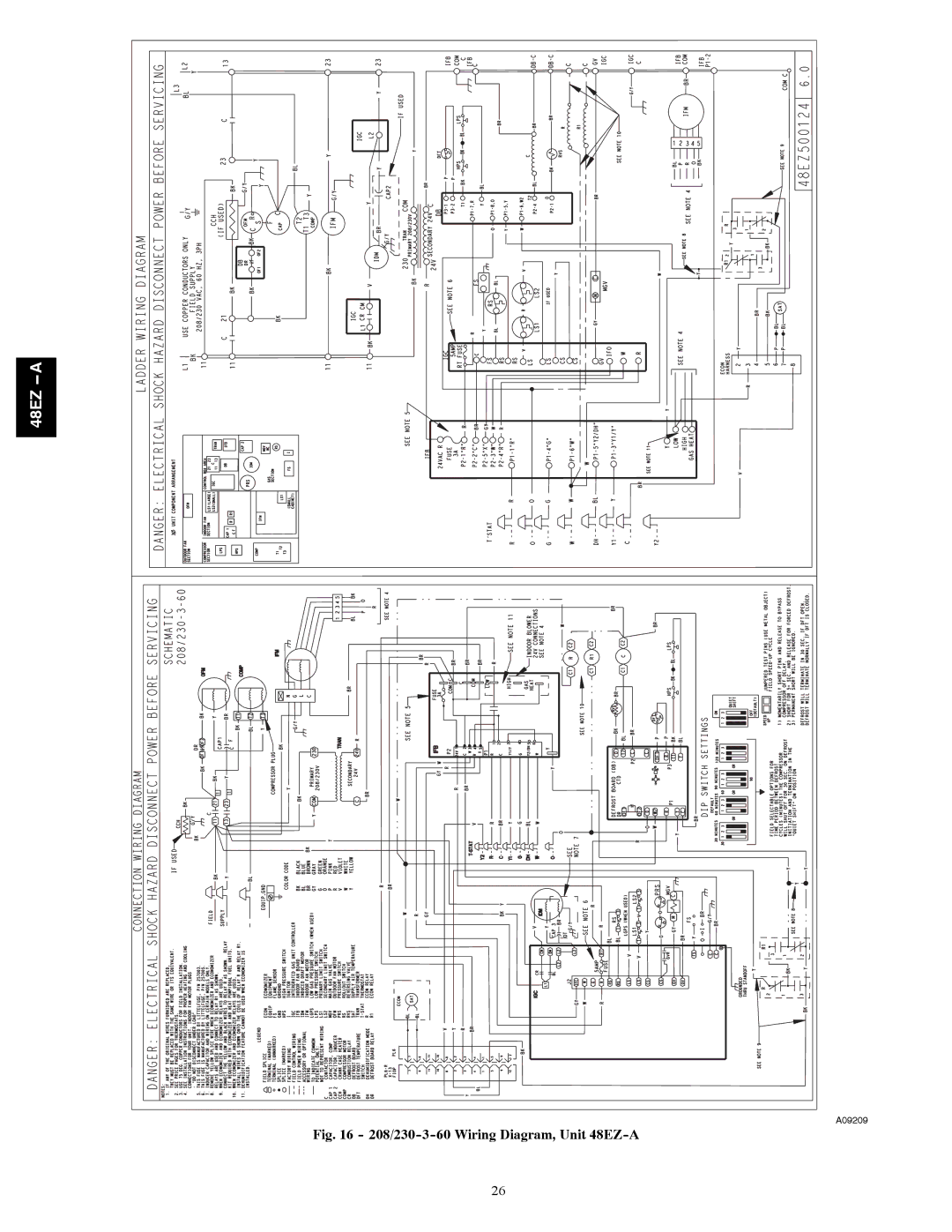
Moreover, both models are equipped for easy installation and serviceability. The logical wiring design and access ports streamline maintenance, reducing downtime and optimizing overall performance. Additionally, they feature an energy-efficient fan design that maximizes airflow while minimizing energy use.
In summary, the Carrier 48EZ-A and 48VT-A rooftop units stand out in the HVAC market for their energy efficiency, advanced technology, and durable construction. These features make them ideal choices for various commercial applications where comfort, efficiency, and reliability are paramount. The combination of high-performance components and user-friendly features positions these models as leaders in modern HVAC solutions.