This configuration provides the following comfort enhance- ments:

(a.) A 30 sec blower on delay with 150 sec at 70 percent airflow to allow the indoor coil to warm up or cool down before the blower is asked to deliver 100 percent airflow reducing the cold blow sensation at start up in heating and allowing the indoor coil to more quickly

EASY SELECT

BOARD TERMINAL

BLOCK

J1

DH

reach wet coil operating conditions in cooling.

(b.) A no blower off delay eliminates cold blow which may be associated with running the blower after shut down of the compressor and avoids re-evaporation of con- densed moisture after cooling/dehumidifying opera-

REMOVE R JUMPER

HUMIDISTAT

A95316

tion.

(c.) Lower airflow while the compressor is running to reduce draft effects and increase heating air tempera- ture and improved humidity control during cooling operation.

ACCESSORY INSTALLATION

a.ACCESSORY ELECTRIC HEATERS

Electric heaters may be installed with the 50GL & 50JZ units per instructions supplied with electric heater package. See unit rating plate for factory-approved electric heater kits.

b.AUXILIARY TERMINALS

The AUX and HUM terminals on the Easy Select™ Board are tied directly to the G terminal, and provide a 24-v. signal whenever the G terminal is energized (See Fig. 12). During Super dehumidify mode, the G signal is not present and the auxiliary terminals are not energized. If the installation includes the use of the operating mode, do not use these terminals to control accessories. See Electronic Air Cleaner and Humidifier sections for further information.

c.ELECTRONIC AIR CLEANER CONNECTIONS

The AUX1 and AUX2 terminals are not always energized during blower operations, as described above. When using an electronic air cleaner with the unit, use Airflow Sensor P/N KEAAC0101AAA. The airflow sensor turns on electronic air cleaner when the blower is operating.

d.HUMIDIFIER/HUMIDISTAT CONNECTIONS

Easy Select™ Board terminals HUM1 and HUM2 are provided for direct connection to the low-voltage control of a humidifier through a standard humidistat (See Fig. 12). These terminals are energized with 24-v. when G thermostat signal is present. (See Fig. 11, 12 & 13). Alternately, the 24-v. signal may be sourced from the W and C circuit board connections. When using a Thermidistat™ Control, Zone Comfort Plus or Comfort Zone II, the 24-v. signal may be sourced directly from the Thermi- distat™ HUM terminal.


HUMIDISTAT

HUM 1


(C)

24-VAC


TO HUMIDIFIER


HUM 2


(G)


HUMIDIFIER WIRING


A95317

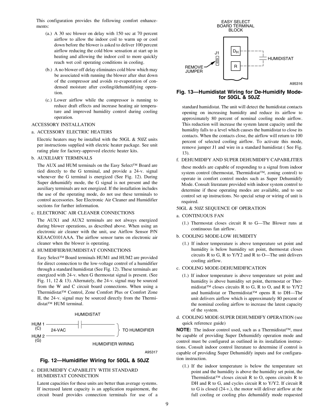
Fig. 12—Humidifier Wiring for 50GL & 50JZ

e.DEHUMIDIFY CAPABILITY WITH STANDARD HUMIDISTAT CONNECTION

Latent capacities for these units are better than average systems. If increased latent capacity is an application requirement, the circuit board provides connection terminals for use of a

Fig. 13—Humidistat Wiring for De-Humidify Mode-

for 50GL & 50JZ

standard humidistat. The unit will detect the humidistat contacts opening on increasing humidity and reduce its airflow to approximately 80 percent of nominal cooling mode airflow. This reduction will increase the system latent capacity until the humidity falls to a level which causes the humidistat to close its contacts. When the contacts close, the airflow will return to 100 percent of selected cooling airflow. To activate this mode, remove jumper J1 and wire in a standard humidistat ( See Fig. 13).

f.DEHUMIDIFY AND SUPER DEHUMIDIFY CAPABILITIES

these models are capable of responding to a signal from indoor system control (thermostat, Thermidistat™, zoning control) to operate in comfort control modes such as Super Dehumidify Mode. Consult literature provided with indoor system control to determine if these operating modes are available, and to see control set up instructions. No special setup or wiring of unit is required.

50GL & 50JZ SEQUENCE OF OPERATION

a.CONTINUOUS FAN

(1.) Thermostat closes circuit R to G—The Blower runs at continuous fan airflow.

b.COOLING MODE-LOW HUMIDITY

(1.) If indoor temperature is above temperature set point and humidity is below humidity set point, thermostat closes circuits R to G, R to Y/Y2 and R to O—The unit delivers cooling airflow.

c.COOLING MODE-DEHUMIDIFICATION

(1.) If indoor temperature is above temperature set point and humidity is above humidity set point, thermostat or Ther- midistat™ closes circuits R to G, R to O, and R to Y/Y2 and humidistat or Thermidistat™ opens R to DH—The unit delivers airflow which is approximately 80 percent of the nominal cooling airflow to increase the latent capacity of the system.

d.COOLING MODE-SUPER DEHUMIDIFY OPERATION (see quick reference guide)

NOTE: The indoor control used, such as a Thermidistat™, must be capable of providing Super Dehumidify operation mode and control must be configured as outlined in its installation instruc- tions. Consult indoor control literature to determine if control is capable of providing Super Dehumidify inputs and for configura- tion instruction.

(1.) If the indoor temperature is below the temperature set point and the humidity is above the humidity set point, the Thermidistat™ closes circuit R to O, opens circuits R to DH and R to G, and cycles circuit R to Y/Y2. If circuit R to G is closed (24-v.), the motor will deliver airflow at the full cooling or cooling plus dehumidify mode requested

9

Page 9
Image 9
Carrier 48JZ (N) 024-060, 50GL 024-060, 50JZ 024-060 Humidifier Wiring for 50GL & 50JZ, 50GL & 50JZ Sequence of Operation

48JZ (N) 024-060, 50JZ 024-060, 48GP (N) 024-060, 50GL 024-060 specifications

The Carrier 50GL 024-060, 48GP (N) 024-060, 50JZ 024-060, and 48JZ (N) 024-060 units are part of Carrier’s advanced HVAC solutions, offering efficient cooling and heating systems designed for both residential and light commercial applications. These models are known for their reliability, energy efficiency, and innovative technology, making them a popular choice for users looking to enhance comfort while reducing operational costs.

One of the main features of the Carrier 50GL series is its use of high-efficiency compressors. These compressors are engineered to operate quietly and effectively, providing optimal performance even during peak load conditions. Additionally, they are equipped with smart features that allow for precise temperature control and improved energy savings, often exceeding standard performance metrics.

The 48GP (N) units are particularly notable for their compact design, making them ideal for installations where space is a limitation. Despite their smaller footprint, they boast significant cooling and heating capacities, ensuring consistent comfort. The use of advanced variable-speed technology in these units helps to maintain consistent indoor temperatures while minimizing energy consumption.

The 50JZ and 48JZ (N) models incorporate advanced inverter technology, allowing for variable refrigerant flow. This technology adjusts the system's output according to the demand, resulting in lower energy usage and increased comfort levels. Additionally, these units feature enhanced filtration systems that improve indoor air quality by capturing airborne pollutants, allergens, and other contaminants.

Another key characteristic of these Carrier units is their durability. Built with high-quality materials, they are designed to withstand harsh environmental conditions, ensuring longevity and reduced maintenance requirements. Furthermore, the installation process is simplified, thanks to user-friendly design features that promote easy serviceability and accessibility.

Overall, the Carrier 50GL 024-060, 48GP (N) 024-060, 50JZ 024-060, and 48JZ (N) 024-060 HVAC units stand out in the industry for their advanced features, energy efficiency, and robust performance. They offer a comprehensive solution for anyone seeking reliable temperature control and improved indoor air quality in a variety of settings.