50TCQA

enthalpy sensor and the (SR) terminal on the enthalpy controller.

NOTE: The enthalpy control must be set to the “D” setting for differential enthalpy control to work properly.

Indoor Air Quality (CO2 sensor) — The indoor air quality sensor accessory monitors space carbon dioxide (CO2) levels. This information is used to monitor IAQ levels. Several types of sensors are available, for wall mounting in the space or in return duct, with and without LCD display, and in combination with space temperature sensors. Sensors use infrared technology to measure the levels of CO2 present in the space air.

The CO2 sensors are all factory set for a range of 0 to 2000 ppm and a linear mA output of 4 to 20. Refer to the instructions supplied with the CO2 sensor for electrical requirements and terminal locations. See Fig. 38 for typical CO2 sensor wiring schematic.

To accurately monitor the quality of the air in the conditioned air space, locate the sensor near a return-air grille (if present) so it senses the concentration of CO2 leaving the space. The sensor should be mounted in a location to avoid direct breath contact.

Do not mount the IAQ sensor in drafty areas such as near supply ducts, open windows, fans, or over heat sources. Allow at least 3 ft (0.9 m) between the sensor and any corner. Avoid mounting the sensor where it is influenced by the supply air; the sensor gives inaccurate readings if the supply air is blown directly onto the sensor or if the supply air does not have a chance to mix with the room air before it is drawn into the return airstream.

Wiring the Indoor Air Quality Sensor —

For each sensor, use two 2-conductor 18 AWG (American Wire Gage) twisted-pair cables (unshielded) to connect the separate isolated 24 vac power source to the sensor and to connect the sensor to the control board terminals.

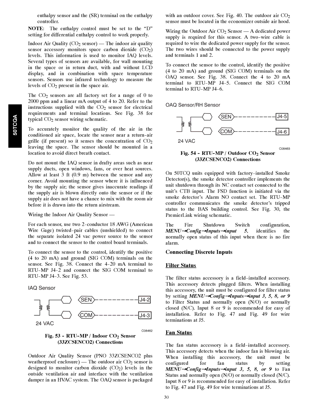
To connect the sensor to the control, identify the positive (4 to 20 mA) and ground (SIG COM) terminals on the sensor. See Fig. 38. Connect the 4-20 mA terminal to RTU-MP J4-2 and connect the SIG COM terminal to RTU-MP J4-3. See Fig. 53.

IAQ Sensor

SEN J4-2

COM J4-3 24 VAC

C08462

Fig. 53 - RTU-MP / Indoor CO2 Sensor

(33ZCSENCO2) Connections

Outdoor Air Quality Sensor (PNO 33ZCSENCO2 plus weatherproof enclosure) — The outdoor air CO2 sensor is designed to monitor carbon dioxide (CO2) levels in the outside ventilation air and interface with the ventilation damper in an HVAC system. The OAQ sensor is packaged

with an outdoor cover. See Fig. 40. The outdoor air CO2 sensor must be located in the economizer outside air hood.

Wiring the Outdoor Air CO2 Sensor — A dedicated power supply is required for this sensor. A two-wire cable is required to wire the dedicated power supply for the sensor. The two wires should be connected to the power supply and terminals 1 and 2.

To connect the sensor to the control, identify the positive (4 to 20 mA) and ground (SIG COM) terminals on the OAQ sensor. See Fig. 38. Connect the 4 to 20 mA terminal to RTU-MP J4-5. Connect the SIG COM terminal to RTU-MP J4-6.

OAQ Sensor/RH Sensor

SEN J4-5

COM J4-6

24 VAC

C08463

Fig. 54 - RTU-MP / Outdoor CO2 Sensor

(33ZCSENCO2) Connections

On 50TCQ units equipped with factory-installed Smoke Detector(s), the smoke detector controller implements the unit shutdown through its NC contact set connected to the unit’s CTB input. The FSD function is initiated via the smoke detector’s Alarm NO contact set. The RTU-MP controller communicates the smoke detector’s tripped status to the BAS building control. See Fig. 30, the PremierLink wiring schematic.

The Fire Shutdown Switch configuration, MENUConfigInputsinput 5, identifies the normally open status of this input when there is no fire alarm.

Connecting Discrete Inputs

Filter Status

The filter status accessory is a field-installed accessory. This accessory detects plugged filters. When installing this accessory, the unit must be configured for filter status by setting MENUConfigInputsinput 3, 5, 8, or 9 to Filter Status and normally open (N/O) or normally closed (N/C). Input 8 or 9 is recommended for easy of installation. Refer to Fig. 47 and Fig. 49 for wire terminations at J5.

Fan Status

The fan status accessory is a field-installed accessory. This accessory detects when the indoor fan is blowing air. When installing this accessory, the unit must be

configured for fan status by setting MENUConfigInputsinput 3, 5, 8, or 9 to Fan Status and normally open (N/O) or normally closed (N/C). Input 8 or 9 is recommended for easy of installation. Refer to Fig. 47 and Fig. 49 for wire terminations at J5.

30

Page 30
Image 30
Carrier 50TCQA installation instructions Connecting Discrete Inputs Filter Status, Fan Status

50TCQA specifications

The Carrier 50TCQA is a split system air conditioner known for its efficiency, reliability, and innovative technology. Designed for commercial and residential applications, this model provides a solution that combines comfort with cost-effectiveness, making it a popular choice for homeowners and businesses alike.

One of the key features of the Carrier 50TCQA is its impressive SEER (Seasonal Energy Efficiency Ratio) rating, which ensures optimal energy efficiency. This means that users can enjoy lower utility bills while maintaining a comfortable indoor climate. The unit is engineered to perform well even in extreme temperatures, providing effective cooling and heating when needed.

This model employs a scroll compressor, which is known for its durability and quiet operation. The compressor's design allows for smoother operation and reduced noise levels, making it suitable for use in noise-sensitive environments. Additionally, the 50TCQA is equipped with a multi-speed fan, allowing for adjustable airflow to match the specific comfort requirements of different spaces.

The Carrier 50TCQA utilizes advanced refrigerant technology, specifically the environmentally friendly R-410A refrigerant. This refrigerant helps to reduce greenhouse gas emissions and provides efficient cooling without depleting the ozone layer. The unit's design is also focused on minimizing refrigerant leaks, ensuring environmental safety and reliability over the long term.

Ease of installation and maintenance is another significant characteristic of the Carrier 50TCQA. The unit features a compact and lightweight design, making it easier for technicians to install and service. Moreover, the system is equipped with diagnostic capabilities that allow for quick identification of issues, enhancing service efficiency and reducing downtime.

In terms of control, the Carrier 50TCQA offers a sophisticated thermostat option that includes programmable settings. Users can easily set desired temperatures, timers, and operating modes, ensuring optimal comfort throughout the day and night.

Overall, the Carrier 50TCQA presents a robust solution for climate control needs. With its energy-efficient performance, advanced technologies, and user-friendly features, it embodies Carrier's commitment to providing high-quality heating and cooling solutions that cater to modern lifestyle requirements. This model stands out as an excellent option for those looking to invest in a reliable HVAC system that enhances comfort while being mindful of energy consumption and environmental considerations.