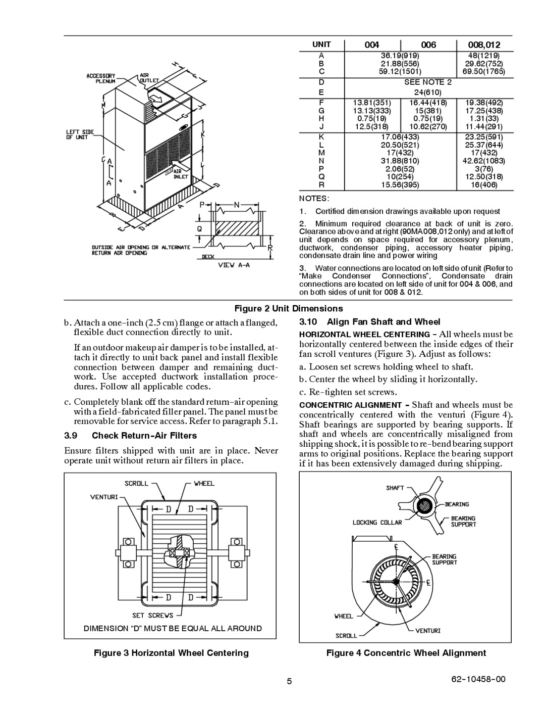
90MA/MF/MU specifications
The Carrier 90MA/MF/MU series represents a significant advancement in HVAC technology, designed for commercial applications needing reliability, efficiency, and precision in climate control. These units are renowned for their ability to cater to varying thermal loads while minimizing energy consumption, making them an ideal choice for various settings including offices, retail spaces, and industrial facilities.One of the standout features of the Carrier 90MA/MF/MU series is its impressive energy efficiency. The equipment is designed with advanced thermodynamic principles to ensure maximum heat transfer and minimal energy loss. With high Seasonal Energy Efficiency Ratios (SEER) and Energy Efficiency Ratios (EER), these units help building owners achieve higher energy savings compared to traditional HVAC systems.
Another significant characteristic of the 90MA/MF/MU series is the integration of advanced control technologies. The units come equipped with sophisticated microprocessor-based controls that allow for precise temperature management and enhance overall system performance. Features like modulating capabilities and variable speed fans provide superior comfort levels by continuously adjusting to the changing environmental conditions.
The 90MA series also emphasizes quiet operation, which is critical for commercial environments. The innovative design includes insulation and vibration dampening technologies that reduce noise levels, ensuring a comfortable working atmosphere.
Durability and reliability are also central to the design of the Carrier 90MA/MF/MU series. These units are engineered with high-quality materials and components, including robust compressors and corrosion-resistant finishes that withstand harsh weather conditions. This durability extends the lifespan of the units, thus reducing maintenance costs and downtime.
In terms of versatility, the 90MA/MF/MU series offers a broad range of configurations and options, including various sizes and capacities. This flexibility allows for tailored solutions that meet the specific needs of different applications, from large commercial buildings to smaller retail outlets.
The series also supports environmentally friendly refrigerants that comply with global standards, marking Carrier’s commitment to sustainable practices. This approach not only reduces environmental impact but also positions businesses favorably in the eyes of eco-conscious consumers.
Overall, the Carrier 90MA/MF/MU series stands out as a pinnacle of efficiency, performance, and reliability in the commercial HVAC market. Its advanced technologies and thoughtful design cater to the diverse needs of modern businesses while promoting a sustainable and comfortable indoor environment.

