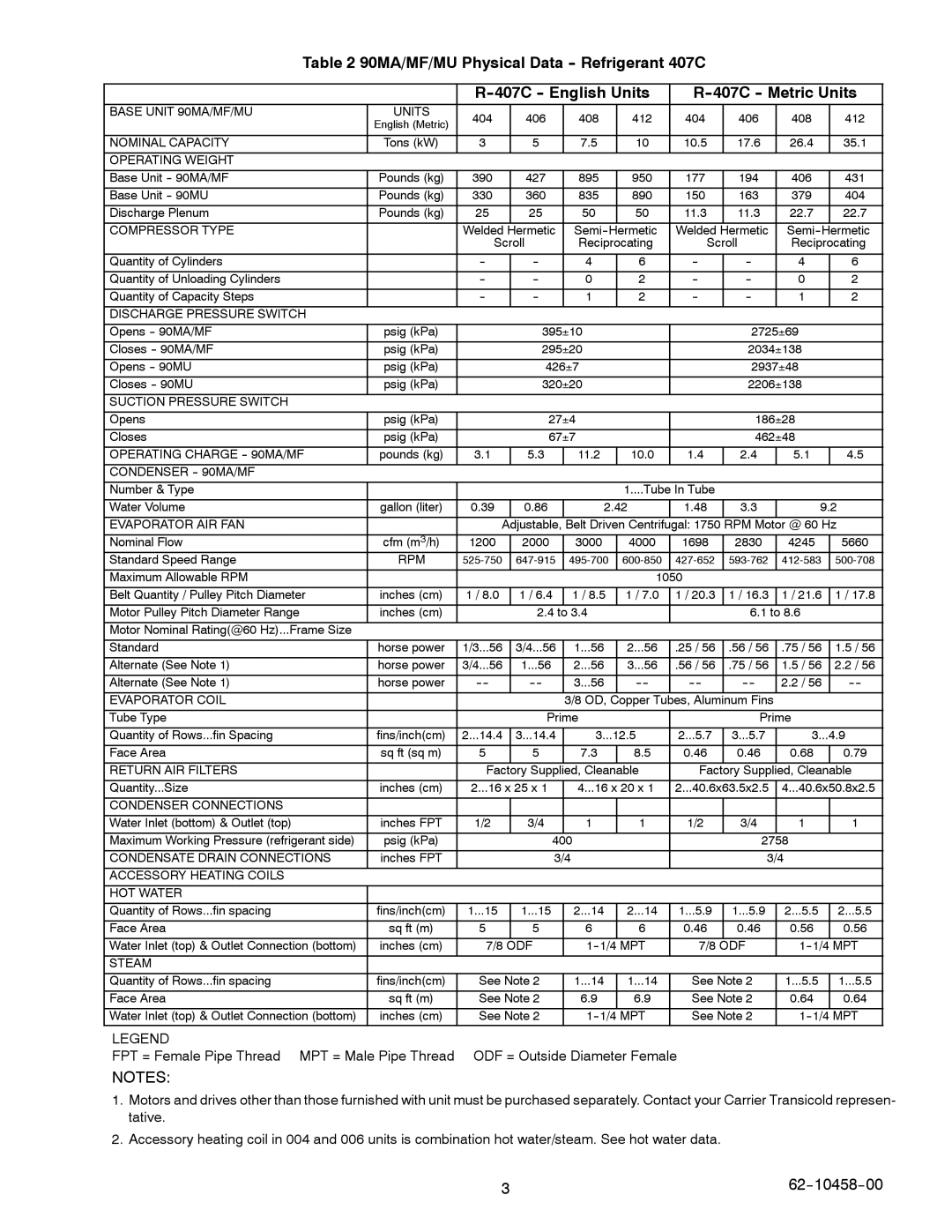
Table 2 90MA/MF/MU Physical Data -- Refrigerant 407C


R--407C -- English Units

R--407C -- Metric Units

BASE UNIT 90MA/MF/MU

UNITS

404

406

408

412

404

406

408

412


English (Metric)


NOMINAL CAPACITY

Tons (kW)

3

5

7.5

10

10.5

17.6

26.4

35.1

OPERATING WEIGHT


Base Unit -- 90MA/MF

Pounds (kg)

390

427

895

950

177

194

406

431

Base Unit -- 90MU

Pounds (kg)

330

360

835

890

150

163

379

404

Discharge Plenum

Pounds (kg)

25

25

50

50

11.3

11.3

22.7

22.7

COMPRESSOR TYPE


Welded

Hermetic

Semi--

Hermetic

Welded

Hermetic

Semi--

Hermetic


Scroll

Reciprocating

Scroll

Reciprocating


Quantity of Cylinders


--

--

4

6

--

--

4

6

Quantity of Unloading Cylinders


--

--

0

2

--

--

0

2

Quantity of Capacity Steps


--

--

1

2

--

--

1

2

DISCHARGE PRESSURE SWITCH


Opens -- 90MA/MF

psig (kPa)


395￿10


2725￿69


Closes -- 90MA/MF

psig (kPa)


295￿20


2034￿138


Opens -- 90MU

psig (kPa)


426￿7


2937￿48


Closes -- 90MU

psig (kPa)


320￿20


2206￿138


SUCTION PRESSURE SWITCH


Opens

psig (kPa)


27￿4


186￿28


Closes

psig (kPa)


67￿7


462￿48


OPERATING CHARGE -- 90MA/MF

pounds (kg)

3.1

5.3

11.2

10.0

1.4

2.4

5.1

4.5

CONDENSER -- 90MA/MF


Number & Type


1....Tube In Tube


Water Volume

gallon (liter)

0.39

0.86

2.42

1.48

3.3

9.2

EVAPORATOR AIR FAN


Adjustable,

Belt Driven Centrifugal: 1750 RPM Motor @ 60 Hz

Nominal Flow

cfm (m3/h)

1200

2000

3000

4000

1698

2830

4245

5660

Standard Speed Range

RPM

525-750

647-915

495-700

600-850

427-652

593-762

412-583

500-708

Maximum Allowable RPM


1050


Belt Quantity / Pulley Pitch Diameter

inches (cm)

1 / 8.0

1 / 6.4

1 / 8.5

1 / 7.0

1 / 20.3

1 / 16.3

1 / 21.6

1 / 17.8

Motor Pulley Pitch Diameter Range

inches (cm)


2.4 to 3.4


6.1 to 8.6


Motor Nominal Rating(@60 Hz)...Frame Size


Standard

horse power

1/3...56

3/4...56

1...56

2...56

.25 / 56

.56 / 56

.75 / 56

1.5 / 56

Alternate (See Note 1)

horse power

3/4...56

1...56

2...56

3...56

.56 / 56

.75 / 56

1.5 / 56

2.2 / 56

Alternate (See Note 1)

horse power

----

----

3...56

----

----

----

2.2 / 56

----

EVAPORATOR COIL


3/8 OD,

Copper Tubes, Aluminum Fins


Tube Type


Prime


Prime


Quantity of Rows...fin Spacing

fins/inch(cm)

2...14.4

3...14.4

3...12.5

2...5.7

3...5.7

3...4.9

Face Area

sq ft (sq m)

5

5

7.3

8.5

0.46

0.46

0.68

0.79

RETURN AIR FILTERS


Factory Supplied, Cleanable

Factory Supplied, Cleanable

Quantity...Size

inches (cm)

2...16 x 25 x 1

4...16 x 20 x 1

2...40.6x63.5x2.5

4...40.6x50.8x2.5

CONDENSER CONNECTIONS


Water Inlet (bottom) & Outlet (top)

inches FPT

1/2

3/4

1

1

1/2

3/4

1

1

Maximum Working Pressure (refrigerant side)

psig (kPa)


400


2758


CONDENSATE DRAIN CONNECTIONS

inches FPT


3/4


3/4


ACCESSORY HEATING COILS


HOT WATER


Quantity of Rows...fin spacing

fins/inch(cm)

1...15

1...15

2...14

2...14

1...5.9

1...5.9

2...5.5

2...5.5

Face Area

sq ft (m)

5

5

6

6

0.46

0.46

0.56

0.56

Water Inlet (top) & Outlet Connection (bottom)

inches (cm)

7/8

ODF

1--1/4

MPT

7/8

ODF

1--1/4

MPT

STEAM


Quantity of Rows...fin spacing

fins/inch(cm)

See Note 2

1...14

1...14

See Note 2

1...5.5

1...5.5

Face Area

sq ft (m)

See Note 2

6.9

6.9

See Note 2

0.64

0.64

Water Inlet (top) & Outlet Connection (bottom)

inches (cm)

See Note 2

1--1/4

MPT

See Note 2

1--1/4

MPT

LEGEND


FPT = Female Pipe Thread MPT = Male Pipe Thread

ODF = Outside Diameter Female


NOTES:

1.Motors and drives other than those furnished with unit must be purchased separately. Contact your Carrier Transicold represen- tative.

2.Accessory heating coil in 004 and 006 units is combination hot water/steam. See hot water data.

3

62--10458--00

Page 9
Image 9
Carrier 90MA/MF/MU manual 404 406 408

90MA/MF/MU specifications

The Carrier 90MA/MF/MU series represents a significant advancement in HVAC technology, designed for commercial applications needing reliability, efficiency, and precision in climate control. These units are renowned for their ability to cater to varying thermal loads while minimizing energy consumption, making them an ideal choice for various settings including offices, retail spaces, and industrial facilities.

One of the standout features of the Carrier 90MA/MF/MU series is its impressive energy efficiency. The equipment is designed with advanced thermodynamic principles to ensure maximum heat transfer and minimal energy loss. With high Seasonal Energy Efficiency Ratios (SEER) and Energy Efficiency Ratios (EER), these units help building owners achieve higher energy savings compared to traditional HVAC systems.

Another significant characteristic of the 90MA/MF/MU series is the integration of advanced control technologies. The units come equipped with sophisticated microprocessor-based controls that allow for precise temperature management and enhance overall system performance. Features like modulating capabilities and variable speed fans provide superior comfort levels by continuously adjusting to the changing environmental conditions.

The 90MA series also emphasizes quiet operation, which is critical for commercial environments. The innovative design includes insulation and vibration dampening technologies that reduce noise levels, ensuring a comfortable working atmosphere.

Durability and reliability are also central to the design of the Carrier 90MA/MF/MU series. These units are engineered with high-quality materials and components, including robust compressors and corrosion-resistant finishes that withstand harsh weather conditions. This durability extends the lifespan of the units, thus reducing maintenance costs and downtime.

In terms of versatility, the 90MA/MF/MU series offers a broad range of configurations and options, including various sizes and capacities. This flexibility allows for tailored solutions that meet the specific needs of different applications, from large commercial buildings to smaller retail outlets.

The series also supports environmentally friendly refrigerants that comply with global standards, marking Carrier’s commitment to sustainable practices. This approach not only reduces environmental impact but also positions businesses favorably in the eyes of eco-conscious consumers.

Overall, the Carrier 90MA/MF/MU series stands out as a pinnacle of efficiency, performance, and reliability in the commercial HVAC market. Its advanced technologies and thoughtful design cater to the diverse needs of modern businesses while promoting a sustainable and comfortable indoor environment.