Table 1 — Electrical Data — Compressor Motor With Circuit Breaker
|
|
| COMPRESSOR MOTOR DATA |
|
| CIRCUIT BREAKER | |||||||
Compressor | Voltage |
| Maximum | Maximum |
| Motor | Recommended |
|
|
|
| ||
|
| Winding |
|
|
| Recommended | |||||||
Part | (3 Ph - 60 Hz) | Hp | Must Trip | RLA | (first | Resistance | Circuit Breaker | MHA | MTA | LRA | RLA | ||
Number 06E |
|
| Amps |
|
| winding) | (Ohms) | Part No. |
|
|
|
| |
|
|
|
|
|
|
|
|
|
|
|
|
| |
| 250 | 208/230 |
| 108 | 87 | 345 | 207 | 0.32 | HH83XB336 | 91 | 104 | 350 | 74.3 |
| 575 | 20 | 45 | 36 | 120 | 72 | 2.2 | XA461 | 33 | 38 | 124 | 27.1 | |
|
| 460 |
| 54 | 44 | 173 | 104 | 1.3 | XA424 | 42 | 49 | 175 | 35.0 |
| 265 | 208/230 |
| 140 | 112 | 446 | 268 | 0.27 | HH83XC509 | 110 | 127 | 420 | 90.7 |
| 575 | 25 | 57 | 46 | 164 | 98 | 1.6 | XA469 | 46 | 53 | 164 | 37.9 | |
A |
| 460 |
| 70 | 56 | 223 | 134 | 1.1 | XA426 | 55 | 643 | 210 | 45.7 |
275 | 208/230 |
| 168 | 135 | 506 | 304 | 0.22 | HH83XC539 | 142 | 163 | 507 | 116.4 | |
|
| ||||||||||||
| 575 | 30 | 65 | 52 | 176 | 106 | 1.3 | XA430 | 50 | 58 | 168 | 41.4 | |
|
| 460 |
| 84 | 68 | 253 | 152 | 0.9 | XA425 | 63 | 73 | 210 | 52.1 |
| 299 | 208/230 |
| 236 | 189 | 690 | 414 | 0.15 | HH83XC537 | 187 | 215 | 636 | 153.6 |
| 575 | 40 | 94 | 75 | 276 | 165 | 1.0 | XA551 | 74 | 85 | 236 | 60.7 | |
|
| 460 |
| 118 | 95 | 345 | 207 | 0.58 | XA550 | 92 | 106 | 295 | 75.7 |
| LEGEND |
LRA | — Locked Rotor Amps |
MHA — Must Hold Amps | |
MTA | — |
PW | — |
RLA | — Rated Load Amps |
XL | — |
*Refer to physical data table to match compressor with correct com- pressor or
NOTES:
1.Compressor MTA and RLA values are maximum figures.
2.LRA values for PW second winding = 1/2 the LRA – XL value.
3.
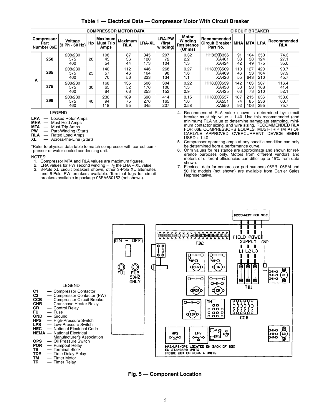
| LEGEND |
C1 | — Compressor Contactor |
C2 | — Compressor Contactor (PW) |
CCB | — Compressor Circuit Breaker |
CHR | — Crankcase Heater Relay |
CR | — Control Relay |
FU | — Fuse |
GND | — Ground |
HPS | — |
LPS | — |
NEC | — National Electrical Code |
NEMA — National Electrical | |
| Manufacturer’s Association |
OPS | — Oil Pressure Switch |
POR | — Pumpout Relay |
TB | — Terminal Block |
TDR | — Time Delay Relay |
TM | — Timer Motor |
TR | — Timer Relay |
4.Recommended RLA value shown is determined by: circuit breaker must trip value ⎟ 1.40. Use this recommended (and minimum) RLA value to determine nameplate stamping, mini- mum contactor sizing, and wire sizing. RECOMMENDED RLA FOR 06E COMPRESSORS EQUALS:
CARLYLE APPROVED OVERCURRENT DEVICE BEING USED ⎟ 1.40
5.Compressor operating amps at any specific condition can only be determined from a performance curve.
6.Ohm values for resistance are approximate and shown for ref- erence purposes only. Motors from different vendors and motors of different efficiencies can differ up to 15% from data shown.
7.Electrical data for compressor part numbers 06ER, 06EM and 50 Hz models (not shown) are available from Carrier Sales Representative.
Fig. 5 — Component Location
5