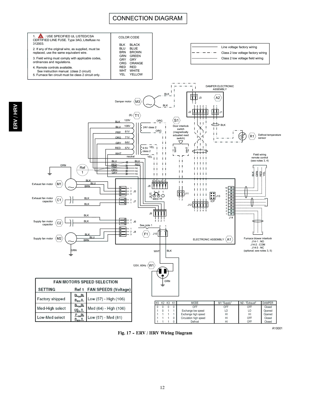
CONNECTION DIAGRAM

1. : USE SPECIFIED UL LISTED/CSA CERTIFIED LINE FUSE. Type 3AG, Littelfuse no 312003.

2.If any of the original wire, as supplied, must be replaced, use the same equivalent wire.

3.Field wiring must comply with applicable codes, ordinances and regulations.

4.Remote controls available.

See instruction manual. (class 2 circuit)

5. Furnace fan circuit must be class 2 circuit only.

COLOR CODE

BLK BLACK BLU BLUE BRN BROWN GRN GREEN GRY GRY ORG ORANGE RED RED WHT WHITE YEL YELLOW

Line voltage factory wiring

Class 2 low voltage factory wiring

Class 2 low voltage field wiring

ERV / HRV


DAMPER ELECTRONIC


ASSEMBLY


BLK


A2


Damper motor

M3


J3


BLK

1

2


5

4

3

2

1

2

1


(6)

T1


J2


J1


S1


BLK

120V


ORG


BLK


BLU

106V

24V class 2


Door interlock


switch


81V


ORG


PRP


(magnetically


ORG

71V


actuated reed


switch)


GRY

64V


RED

57V

9.5V YEL


WHT

WHT


WHT


class 2


neutral

YEL


BLU


BLU


GRN


RED


RED


Ref

PRP


nc


1


ORG


nc


GRY


nc


BLK


5 4

3

2

1


Exhaust fan motor

M1

BLU


J8


BRN


1


10


2

J5

JU1

3

2

1

J11


J13

9


3


7


8

Exhaust fan motor

C1

BLK


2


MED HI

1

2


ICP


6

capacitor


J7


BLK


1


J12


5


4


1

2

3

4

5


3


J9


2


BLK


1


J14


2


Supply fan motor

C2

BLK


J6


4

3

2

1


1


capacitor


See note 1


2


1


1


BLK


2

J4


J10


3

F1


Supply fan motor

M2

BLU


ELECTRONIC ASSEMBLY

A1

BRN


GRN


WHT


BLK


120V, 60Hz

W1


GRN


to

R1

Defrost temperature


sensor

Field wiring

remote control (see notes 3, 4)

BLK

GRN

RED YEL


Furnace blower interlock

J14-1 : NO

J14-2 : COM

J14-3 : NC

(optional; see notes 3, 5)

K5

K2

K3

K1

MODE

M1 "Supply"

M2 - "Exhaust"

DAMPER

0

0

0

0

OFF

OFF

OFF

Closed

1

0

1

1

Exchange low speed

LO

LO

Opened

1

1

1

1

Exchange high speed

HI

HI

Opened

1

1

1

0

Circulation high speed

HI

OFF

Closed

1

1

1

0

Defrost

HI

OFF

Closed

A10001

Fig. 17 - ERV / HRV Wiring Diagram

12

Page 12
Image 12
Carrier HRVCCSVB1100, ERVCCSHB1100, HRVCCSHB1100, ERVCCSVB1100 installation instructions Connection Diagram

ERVCCSVB1100, HRVCCSHB1100, ERVCCSHB1100, HRVCCSVB1100 specifications

The Carrier ERVCCSVB1100, HRVCCSVB1100, HRVCCSHB1100, and ERVCCSHB1100 represent the latest advancements in residential and commercial ventilation systems. These systems are designed to enhance indoor air quality while ensuring energy efficiency, making them ideal solutions for modern buildings.

One of the main features of these units is their recovery ventilation technology. Both the Energy Recovery Ventilator (ERV) and Heat Recovery Ventilator (HRV) options are engineered to efficiently transfer heat and moisture between incoming and outgoing air streams. This process reduces energy consumption by pre-conditioning fresh air, thereby minimizing the workload on heating and cooling systems.

The ERVCCSVB1100 and ERVCCSHB1100 models are particularly well-suited for humid climates where moisture control is critical. They utilize a sophisticated enthalpy exchange process, which allows excess humidity to be transferred from the stale air to the incoming fresh air, thereby reducing the burden on air conditioning systems and maintaining optimal indoor humidity levels. This feature is essential for enhancing occupant comfort and safeguarding building materials from moisture-related damage.

On the other hand, the HRVCCSVB1100 and HRVCCSHB1100 units shine in drier climates where humidity control is less of a concern. These systems focus on heat recovery, effectively transferring thermal energy without exchanging moisture. This is particularly advantageous during winter months, as they provide fresh air while conserving precious heat, thus optimizing energy utilization and contributing to lower utility bills.

Another critical characteristic of all four models is their quiet operation. Designed with sound-dampening technologies, they ensure minimal noise disturbance, thereby maintaining a peaceful indoor environment. This is especially valuable in residential settings or commercial spaces that require a distraction-free atmosphere.

Additionally, the units come with intelligent controls that allow users to monitor and adjust settings according to their specific needs. Features such as programmable timers and remote access capabilities provide convenience and flexibility for users, enabling them to optimize their indoor air quality effortlessly.

In summary, Carrier's ERVCCSVB1100, HRVCCSVB1100, HRVCCSHB1100, and ERVCCSHB1100 models offer a comprehensive suite of features, advanced technologies, and characteristics tailored to meet the demands of modern indoor environments. By integrating energy recovery ventilation with user-friendly controls, they set a new standard for efficiency, comfort, and air quality in various building types.