Page 6 of 8 | |
ELECTRICAL CONNECTIONS CONTINUED | (NOT USING SWITCH PANEL) |
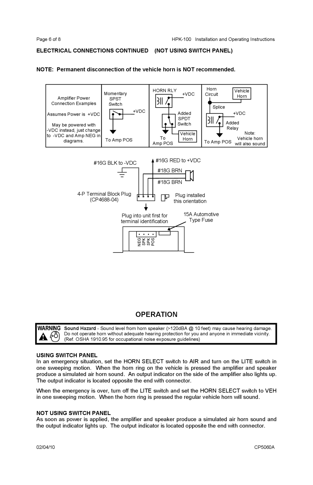
NOTE: Permanent disconnection of the vehicle horn is NOT recommended.
Amplifier Power
Connection Examples
Assumes Power is +VDC
May be powered with
Momentary
SPST
Switch
+VDC
To Amp POS
HORN RLY
+VDC
Added
SPDT
Switch
Vehicle
To Horn
Amp POS
Horn Vehicle
Circuit Horn
Splice
+VDC
Added Relay
Note:
Vehicle horn To Amp POS will also sound
#16G BLK to |
| #16G RED to +VDC | ||||||||
|
|
|
|
| ||||||
|
|
|
|
|
|
| #18G BRN |
|
| |
| #18G BRN |
|
| |||||||
|
|
| ||||||||
| ||||||||||
|
| Plug installed | ||||||||
|
| |||||||||
|
| this orientation | ||||||||
| Plug into unit first for | 15A Automotive | ||||||||
| terminal identification | Type Fuse | ||||||||
NEG SPK SPK POS |
OPERATION
USING SWITCH PANEL
In an emergency situation, set the HORN SELECT switch to AIR and turn on the LITE switch in one sweeping motion. When the horn ring on the vehicle is pressed the amplifier and speaker produce a simulated air horn sound. An output indicator on the side of the amplifier also lights up. The output indicator is located opposite the end with connector.
When the emergency is over, turn off the LITE switch and set the HORN SELECT switch to VEH in one sweeping motion. When the horn ring is pressed the regular vehicle horn will sound.
NOT USING SWITCH PANEL
As soon as power is applied, the amplifier and speaker produce a simulated air horn sound and the output indicator lights up. The output indicator is located opposite the end with connector.
02/04/10 | CP5060A |