Page 2 of 8 | |
TABLE OF CONTENTS |
|
GENERAL DESCRIPTION | 2 |
SPECIFICATIONS | 2 |
INSTALLATION | 3 |
SAFETY PRECAUTIONS | 3 |
UNPACKING | 3 |
OPTION SWITCHES | 4 |
MOUNTING | 5 |
ELECTRICAL CONNECTIONS | 5 |
OPERATION | 6 |
POWER ON/OFF | 6 |
YELP - STANDBY - WAIL SELECTOR SWITCH | 6 |
MANUAL / PHASER - HORN SWITCH | 6 |
AUXILIARY INPUT FUNCTIONS | 6 |
Horn Ring Cycler 2 (HRC2) | 6 |
SERVICE | 7 |
PROBLEMS | 7 |
PARTS and ACCESSORIES | 7 |
RETURNS | 8 |
WARRANTY | 8 |
GENERAL DESCRIPTION
The
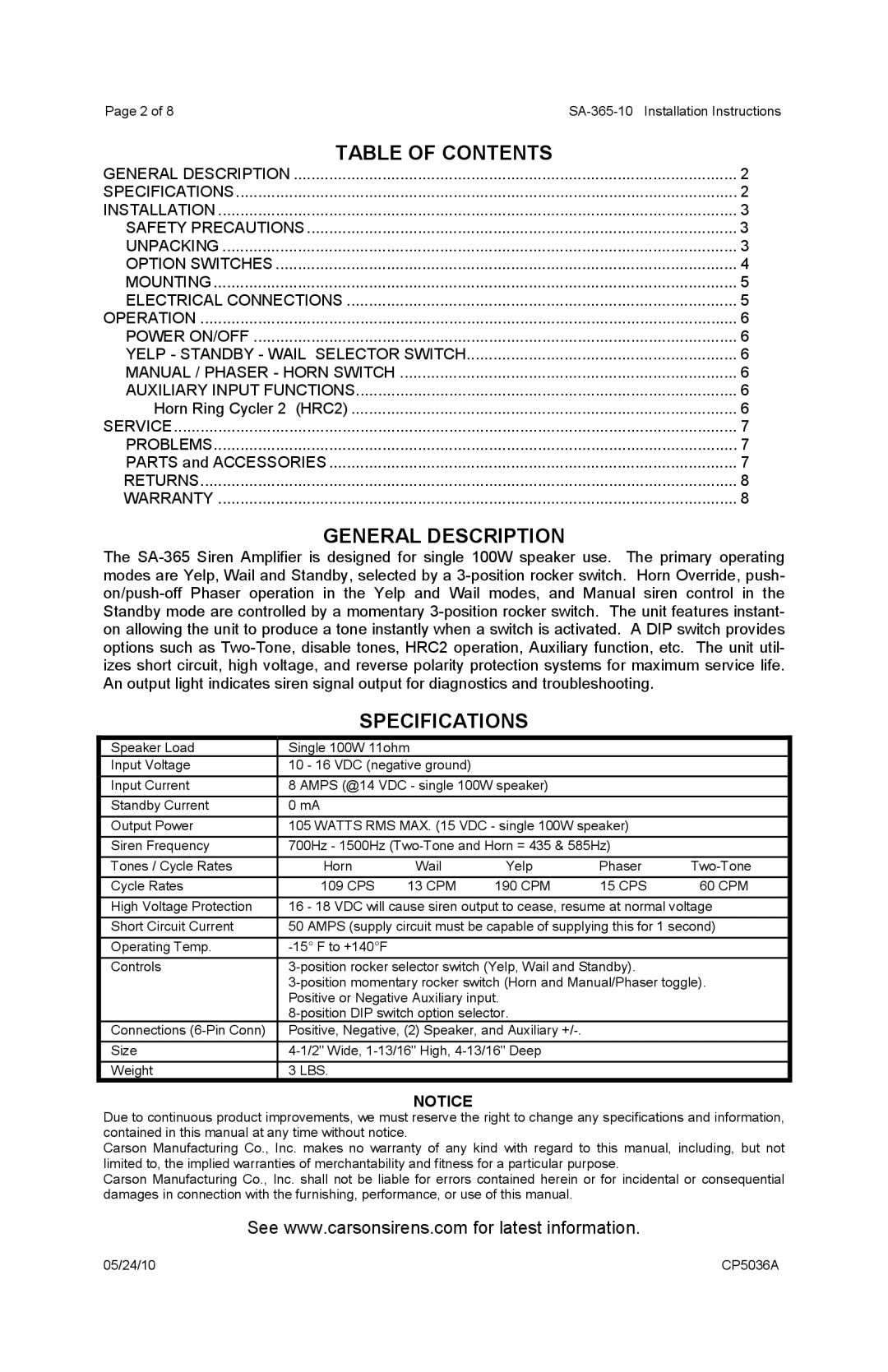
| SPECIFICATIONS |
|
| ||
Speaker Load | Single 100W 11ohm |
|
|
| |
Input Voltage | 10 - 16 VDC (negative ground) |
|
|
| |
Input Current | 8 AMPS (@14 VDC - single 100W speaker) |
|
| ||
Standby Current | 0 mA |
|
|
|
|
Output Power | 105 WATTS RMS MAX. (15 VDC - single 100W speaker) |
| |||
Siren Frequency | 700Hz - 1500Hz |
| |||
Tones / Cycle Rates | Horn | Wail | Yelp | Phaser | |
Cycle Rates | 109 CPS | 13 CPM | 190 CPM | 15 CPS | 60 CPM |
High Voltage Protection | 16 - 18 VDC will cause siren output to cease, resume at normal voltage | ||||
Short Circuit Current | 50 AMPS (supply circuit must be capable of supplying this for 1 second) | ||||
Operating Temp. |
|
|
|
| |
Controls |
| ||||
| |||||
| Positive or Negative Auxiliary input. |
|
| ||
|
|
| |||
Connections | Positive, Negative, (2) Speaker, and Auxiliary |
|
| ||
Size |
|
| |||
Weight | 3 LBS. |
|
|
|
|
NOTICE
Due to continuous product improvements, we must reserve the right to change any specifications and information, contained in this manual at any time without notice.
Carson Manufacturing Co., Inc. makes no warranty of any kind with regard to this manual, including, but not limited to, the implied warranties of merchantability and fitness for a particular purpose.
Carson Manufacturing Co., Inc. shall not be liable for errors contained herein or for incidental or consequential damages in connection with the furnishing, performance, or use of this manual.
See www.carsonsirens.com for latest information.
05/24/10 | CP5036A |