Page 5 of 8 |
MOUNTING
The mounting bracket supplied can be installed above or below the unit. Choose a mounting location convenient to the operator and away from any air bag deployment areas. Inspect behind mounting area for clearance. Assure adequate ventilation to prevent overheating. Consider wire routing and access to connections, as well as microphone bracket placement. Install mounting bracket to vehicle using 1/4" hardware (not supplied). If mounting in a rack or console, make sure that mounting bolts do not enter case more than 1/4".
ELECTRICAL CONNECTIONS
Electrical connections to the unit are made using a removable terminal block plug located on the back. A label on the unit identifies each terminal function. Install the plug on the unit before wiring. If the unit needs service the plug can be easily removed without unwiring. The power supply of the unit must be capable of delivering peak currents up to 50 amps for adequate short circuit protection and reliable operation. The preferred source is directly at the vehicle battery. The unit is fused near connector.
Attach leads by stripping 3/8", inserting into plug and clamp by tightening screw. Make sure the screw is tight and the wire can't be pulled out.
Failure to adequately tighten the screw can result in improper operation or burning the connector and wire.
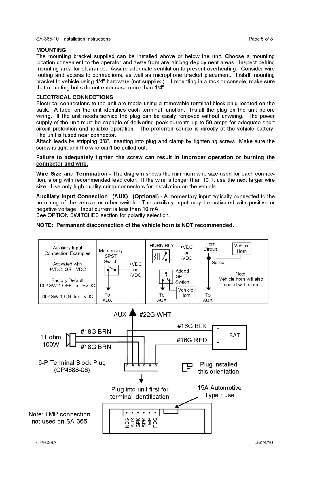
Wire Size and Termination - The diagram shows the minimum wire size used for each connec- tion, along with recommended lead color. If the wire is longer than 10 ft. use the next larger wire size. Use only high quality crimp connectors for installation on the vehicle.
Auxiliary Input Connection (AUX) (Optional) - A momentary input typically connected to the horn ring of the vehicle or other switch. The auxiliary input may be activated with positive or negative voltage. Input current is less than 10 mA.
See OPTION SWITCHES section for polarity selection.
NOTE: Permanent disconnection of the vehicle horn is NOT recommended.
Auxiliary Input
Connection Examples
Momentary
HORN RLY +VDC or
Horn Vehicle
Circuit Horn
Activated with
+VDC OR
Factory Default
DIP
DIP
SPST
Switch
To
AUX
+VDC
or
![]() Added
Added
SPDT
Switch
Vehicle
To Horn
AUX
Splice
Note:
Vehicle horn will also
sound with siren
To
AUX
AUX #22G WHT
11 ohm |
|
| #18G BRN |
| |||
|
|
| |
100W |
|
| #18G BRN |
|
|
|
Plug into unit first for terminal identification
#16G BLK | - |
| |
#16G RED | + |
|
Plug installed this orientation
15A Automotive
Type Fuse
Note: LMP connection
not used on
NEG AUX SPK SPK LMP POS |
CP5036A | 05/24/10 |