CONTROLS AND DISPLAYS
Never make or break connections to the
Do not connect the outputs of the
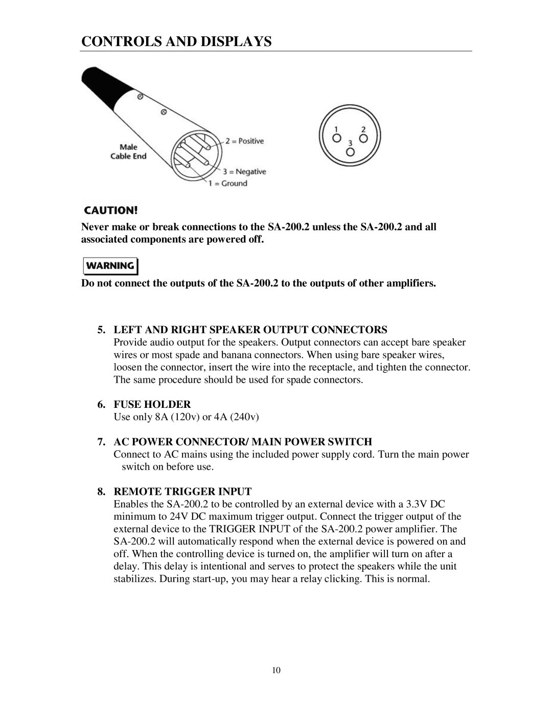
5.LEFT AND RIGHT SPEAKER OUTPUT CONNECTORS
Provide audio output for the speakers. Output connectors can accept bare speaker wires or most spade and banana connectors. When using bare speaker wires, loosen the connector, insert the wire into the receptacle, and tighten the connector. The same procedure should be used for spade connectors.
6.FUSE HOLDER
Use only 8A (120v) or 4A (240v)
7.AC POWER CONNECTOR/ MAIN POWER SWITCH
Connect to AC mains using the included power supply cord. Turn the main power switch on before use.
8.REMOTE TRIGGER INPUT
Enables the
10