E
OPERATING INSTRUCTIONS
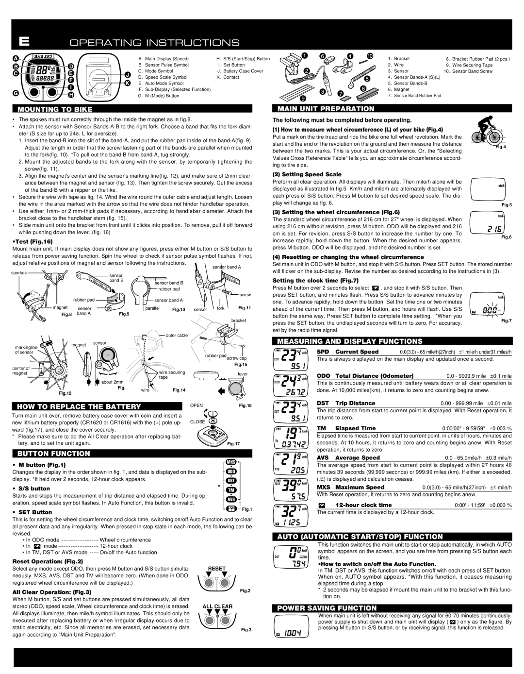
A. | Main Display (Speed) | H. S/S (Start/Stop) Button |
B. | Sensor Pulse Symbol | I. Set Button |
C. | Mode Symbol | J. Battery Case Cover |
D. | Speed Scale Symbol | K. Contact |
E. | Auto Mode Symbol |
|
F. |
| |
G. | M (Mode) Button |
|
1. | Bracket | 8. | Bracket Rubber Pad (2 pcs.) |
2. | Wire | 9. | Wire Securing Tape |
3. | Sensor | 10. | Sensor Band Screw |
4.Sensor
5.Sensor
6.Magnet
7.Sensor Band Rubber Pad
MOUNTING TO BIKE
•The spokes must run correctly through the inside the magnet as in fig.8.
•Attach the sensor with Sensor
1.Insert the
2.Mount the adjusted bands to the fork along with the sensor, by temporarily tightening the screw(fig. 11).
3.Align the magnet's center and the sensor's marking line(fig. 12), and make sure of 2mm clear- ance between the magnet and sensor (fig. 13). Then tighten the screw securely. Cut the excess of the
•Secure the wire with tape as fig. 14. Wind the wire round the outer cable and adjust length. Loosen the wire in the area marked with the arrow so that the wire does not hinder handlebar operation.
•Use either 1mm- or 2
•Slide main unit onto the bracket from front until it clicks into position. To remove, pull it off forward while pushing down the lever. (fig. 16)
•Test (Fig.16)
Mount main unit. If main display does not show any figures, press either M button or S/S button to
MAIN UNIT PREPARATION
The following must be completed before operating.
(1) How to measure wheel circumference (L) of your bike (Fig.4)
Put a mark on the tire tread and ride the bike one full wheel revolution. Mark the start and the end of the revolution on the ground and then measure the distance between the two marks. This is your actual circumference. Or, the "Selecting Values Cross Reference Table" tells you an approximate circumference accord- ing to tire size.
(2) Setting Speed Scale
Preform all clear operation. All displays will illuminate. Then mile/h alone will be displayed as illustrated in fig.5. Km/h and mile/h are alternately displayed with each press of S/S button. Press M button to set desired speed scale. The dis- play will change as fig. 6.
(3) Setting the wheel circumference (Fig.6)
The standard wheel circumference of 216 cm for 27" wheel is displayed. When using 216 cm without revision, press M button. ODO will be displayed and 216 cm is set. For revision, press S/S button to increase the number by one. To increase rapidly, hold down the button. When the desired number appears, press M button. ODO will be displayed, and the desired number is set.
L
Fig.4
Fig.5
Fig.6
release from power saving function. Spin the wheel to check if sensor pulse symbol flashes. If not,
(4) Resetting or changing the wheel circumference
adjust relative positions of magnet and sensor following the instructions.
sporkes |
|
| sensor |
|
|
| |
|
|
| band B |
|
| rubber pad | |
| magnet | sensor |
|
| Fig.8 | band A | Fig.9 |
markingline | magnet | sensor | |
| |||
|
|
| |
of sensor |
|
|
|
center of |
|
|
|
magnet |
|
|
|
|
|
| about 2mm |
|
|
| Fig. |
| Fig.12 |
|
|
|
|
| sensor band A | |
sensor band B |
|
|
| |
rubber pad |
|
|
| |
|
|
|
| screw |
sensor band A |
|
|
| |
parallel | Fig.10 | sensor | fork | Fig.11 |
|
|
|
| bracket |
| outer cable |
|
|
|
|
| rubber padscrew cap | ||
|
|
|
| Fig.15 |
wire securing |
|
| lever | |
tape |
|
| ||
|
|
| ||
wire | Fig.14 |
|
|
|
HOW TO REPLACE THE BATTERY | OPEN | Fig.16 | |
|
| ||
Turn main unit over, remove battery case cover with coin and insert a |
|
| |
new lithium battery properly (CR1620 or CR1616) with the (+) pole up- CLOSE |
| ||
ward (fig.17), and close the cover securely. |
|
| |
* Please make sure to do the All Clear operation after replacing bat- |
|
| |
tery, and to set the unit again. |
| Fig.17 | |
BUTTON FUNCTION |
|
| |
• M button (Fig.1) |
| MXS | |
|
| ||
Changes the display in the order shown in fig. 1, and data is displayed on the sub- | ODO | ||
display. *If held over 2 seconds, |
| DST | |
• S/S button |
| TM | |
Starts and stops the measurement of trip distance and elapsed time. During op- | AVS | ||
eration, speed scale symbol flashes. In Auto Function, this button is invalid. | |||
| |||
• SET Button
Fig.1
This is for setting the wheel circumference and clock time, switching on/off Auto Function and to clear all present data and any irregularity. When pressed in stop state in each mode, the following can be revised.
•In ODO mode
•In ![]() mode
mode
•In TM, DST or AVS mode
Reset Operation: (Fig.2)
Select any mode except ODO, then press M button and S/S button simulta- | RESET | |
neously. MXS, AVS, DST and TM will become zero. (When done in ODO, |
| |
registered wheel circumference will be displayed.) |
| |
All Clear Operation: (Fig.3) | Fig.2 | |
When M button, S/S and set buttons are pressed simultaneously, all data |
| |
stored (ODO, speed scale, Wheel circumference and clock time) is erased. | ALL CLEAR | |
All displays illuminate, then mile/h symbol illuminates. This should only be |
| |
executed after replacing battery or when irregular display occurs due to |
| |
static electricity, etc. Since all memories are erased, set necessary data | Fig.3 | |
again according to "Main Unit Preparation". | ||
|
Set main unit in ODO with M button, and stop it with S/S button. Press SET button. The stored number will flicker on the
Setting the clock time (Fig.7)
Press M button over 2 seconds to select ![]() , and stop it with S/S button. Then press SET button, and minutes flash. Press S/S button to advance minutes by one. To advance rapidly, hold down the button. Set the time one or two minutes ahead of the current time. Then press M button, and hours will flash. Use S/S button the same way. Press SET button to complete time setting. *When you
, and stop it with S/S button. Then press SET button, and minutes flash. Press S/S button to advance minutes by one. To advance rapidly, hold down the button. Set the time one or two minutes ahead of the current time. Then press M button, and hours will flash. Use S/S button the same way. Press SET button to complete time setting. *When you
press the SET button, the undisplayed seconds will turn to zero. For accuracy, | Fig.7 |
| |
set by the radio time signal. |
|
MEASURING AND DISPLAY FUNCTIONS
| SPD | Current Speed | 0.0(3.0) - 65 mile/h(27inch) ± 1 mile/h under31 miles/h | ||||
DST | This is always displayed on the main display and updated once a second. |
|
| ||||
| ODO | Total Distance (Odometer) | 0.0 - 9999.9 mile ± 0.1 mile | ||||
|
|
|
|
|
|
| |
ODO | This is continuously measured until battery wears down or all clear operation is | ||||||
| |||||||
| done. At 10,000 miles(km), it returns to zero and counting begins anew. | ||||||
| DST | Trip Distance |
| 0.00 - 999.99 mile ± 0.01 mile | |||
DST | The trip distance from start to current point is displayed. With Reset operation, it |
|
| ||||
| returns to zero. |
|
|
|
| ||
| TM | Elapsed Time |
| 0:00'00" - 9:59'59"± 0.003 % |
| ||
| Elapsed time is measured from start to current point, in units of hours, minutes and |
| |||||
TM | seconds. At 10 hours, it returns to zero and counting begins anew. With Reset | ||||||
| |||||||
| operation, it returns to zero. |
|
|
|
| ||
| AVS | Average Speed |
| 0.0 - 65.0mile/h ± 0.3 mile/h | |||
AVS | The average speed from start to current point is displayed within 27 hours 46 |
| |||||
minutes 39 seconds (99,999 seconds) or 999.99 miles (km). If either is exceeded, | |||||||
| |||||||
MXS | (.E) is displayed and calculation ceases. |
|
|
| |||
MXS | Maximum Speed |
| 0.0(3.0) - 65 mile/h(27inch) ± 1 mile/h | ||||
|
| ||||||
| With Reset operation, it returns to zero and counting begins anew. |
| |||||
|
|
| 0:00' - 11:59'± 0.003 % | ||||
The current time is displayed by a
AUTO (AUTOMATIC START/STOP) FUNCTION
|
| This function switches the main unit to start or stop automatically, in which AUTO |
|
| symbol appears on the screen, and you are free from pressing S/S button each |
DST | AUTO | time. |
| ||
|
| •How to switch on/off the Auto Function. |
In TM, DST or AVS, this function switches on/off with each press of SET button. When on, AUTO symbol appears. *With this function, it ceases measuring elapsed time during a stop.
*2 seconds may be elapsed if mount the main unit to the bracket with this func- tion on.
POWER SAVING FUNCTION
When main unit is left without receiving any signal for ![]() ) only as the figure. By pressing M button or S/S button, or by receiving signal, this function is released.
) only as the figure. By pressing M button or S/S button, or by receiving signal, this function is released.