GAS CONNECTOR | GB Cat: II 2H3+ |
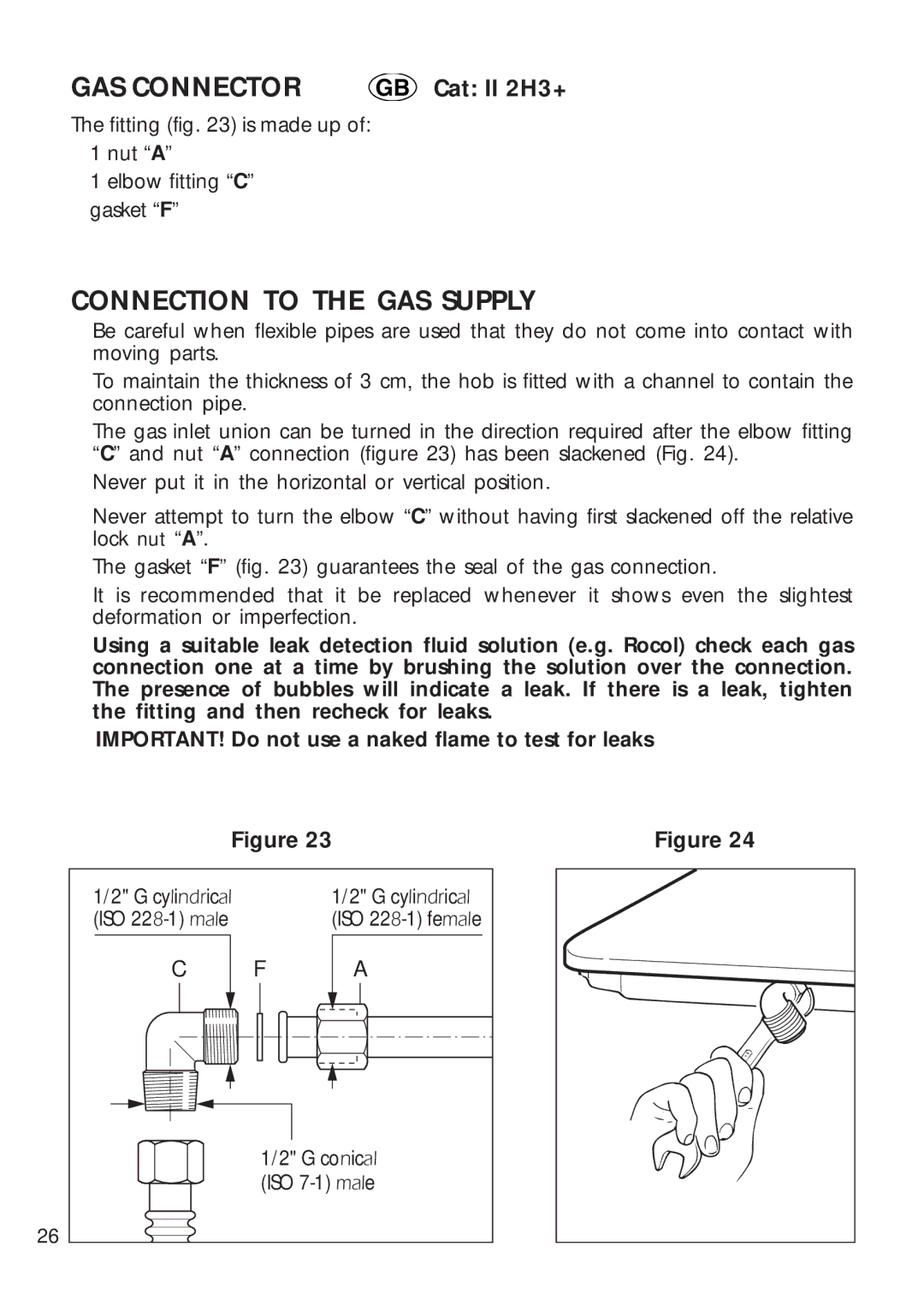
The fitting (fig. 23) is made up of:
✓1 nut “A”
✓1 elbow fitting “C”
✓gasket “F”
CONNECTION TO THE GAS SUPPLY
✓Be careful when flexible pipes are used that they do not come into contact with moving parts.
✓To maintain the thickness of 3 cm, the hob is fitted with a channel to contain the connection pipe.
✓The gas inlet union can be turned in the direction required after the elbow fitting “C” and nut “A” connection (figure 23) has been slackened (Fig. 24).
✓Never put it in the horizontal or vertical position.
✓Never attempt to turn the elbow “C” without having first slackened off the relative lock nut “A”.
✓The gasket “F” (fig. 23) guarantees the seal of the gas connection.
It is recommended that it be replaced whenever it shows even the slightest deformation or imperfection.
✓Using a suitable leak detection fluid solution (e.g. Rocol) check each gas connection one at a time by brushing the solution over the connection. The presence of bubbles will indicate a leak. If there is a leak, tighten the fitting and then recheck for leaks.
IMPORTANT! Do not use a naked flame to test for leaks
Figure 23 | Figure 24 |
1/2" G cylindrical |
| 1/2" G cylindrical |
(ISO |
| (ISO |
C | F | A |
| 1/2" G conical | |
| (ISO | |
26 |
|
|