ASSEMBLY INSTRUCTIONS
ASSEMBLY INSTRUCTIONS
5
![]() A + B
A + B
![]() C
C
A
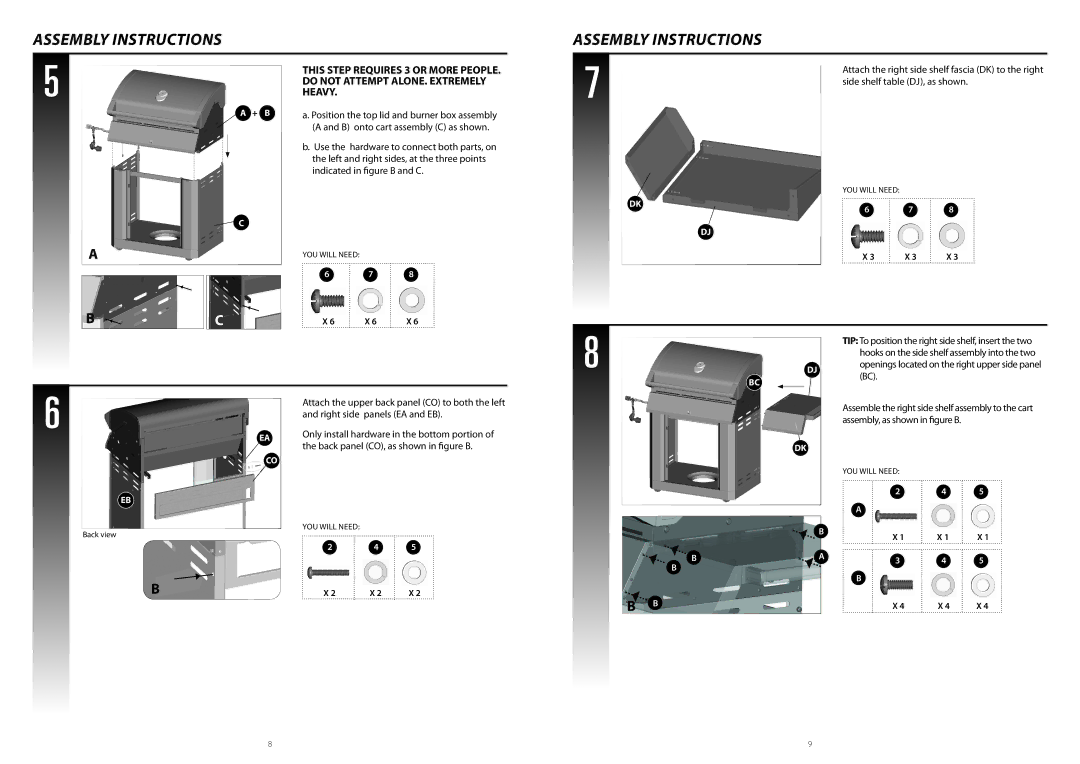
THIS STEP REQUIRES 3 OR MORE PEOPLE. DO NOT ATTEMPT ALONE. EXTREMELY HEAVY.
a. Position the top lid and burner box assembly (A and B) onto cart assembly (C) as shown.
b.Use the hardware to connect both parts, on the left and right sides, at the three points indicated in figure B and C.
YOU WILL NEED:
6 7 8
7 | Attach the right side shelf fascia (DK) to the right |
| |
| side shelf table (DJ), as shown. |
YOU WILL NEED:
DK
6 7 8
DJ
X 3 | X 3 | X 3 |
B |
| C | X 6 | X 6 | X 6 |
|
8
DJ
BC
TIP: To position the right side shelf, insert the two hooks on the side shelf assembly into the two openings located on the right upper side panel (BC).
6
EB
Back view
EA
CO
Attach the upper back panel (CO) to both the left and right side panels (EA and EB).
Only install hardware in the bottom portion of the back panel (CO), as shown in figure B.
YOU WILL NEED:
2 4 5
DK
| B |
B | * |
A | |
B |
|
Assemble the right side shelf assembly to the cart assembly, as shown in figure B.
YOU WILL NEED:
2 4 5
A
X 1 | X 1 | X 1 |
3 4 5
B
B | X 2 | X 2 | X 2 |
B B
X 4 | X 4 | X 4 |
8 | 9 |
