ASSEMBLY INSTRUCTIONS
ASSEMBLY INSTRUCTIONS
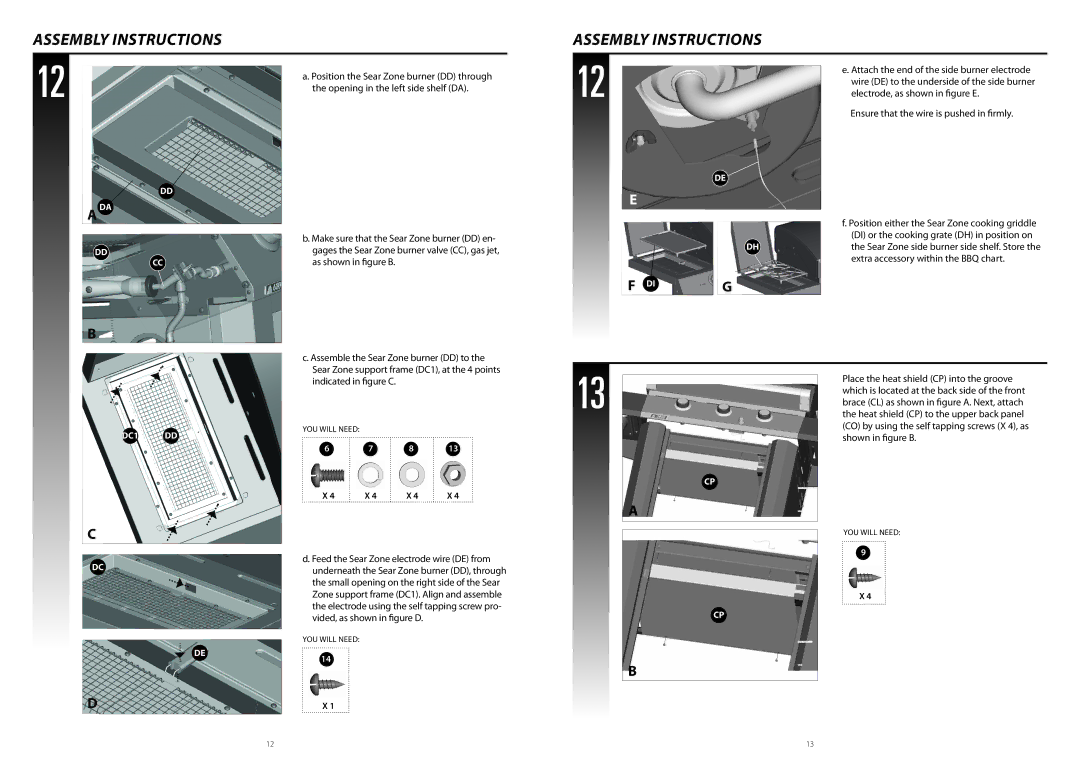
12 | a. Position the Sear Zone burner (DD) through |
| |
| the opening in the left side shelf (DA). |
DD
12
DE
E
e. Attach the end of the side burner electrode wire (DE) to the underside of the side burner electrode, as shown in figure E.
Ensure that the wire is pushed in firmly.
f. Position either the Sear Zone cooking griddle
DD
CC
B
b. Make sure that the Sear Zone burner (DD) en- gages the Sear Zone burner valve (CC), gas jet, as shown in figure B.
(DI) or the cooking grate (DH) in position on
DHthe Sear Zone side burner side shelf. Store the extra accessory within the BBQ chart.
F DI | G |
DC1 DD
c. Assemble the Sear Zone burner (DD) to the Sear Zone support frame (DC1), at the 4 points indicated in figure C.
YOU WILL NEED:
6 7 8 13
13
CP
Place the heat shield (CP) into the groove which is located at the back side of the front brace (CL) as shown in figure A. Next, attach the heat shield (CP) to the upper back panel (CO) by using the self tapping screws (X 4), as shown in figure B.
X 4 X 4 X 4 X 4
C
d. Feed the Sear Zone electrode wire (DE) from
DC |
| underneath the Sear Zone burner (DD), through |
|
| |
|
| the small opening on the right side of the Sear |
|
| Zone support frame (DC1). Align and assemble |
|
| the electrode using the self tapping screw pro- |
|
| vided, as shown in figure D. |
|
| YOU WILL NEED: |
| DE | 14 |
|
| |
D |
| X 1 |
A
YOU WILL NEED:
9
X 4
CP
B
12 | 13 |