ASSEMBLY INSTRUCTIONS
ASSEMBLY INSTRUCTIONS
9 | Front |
|
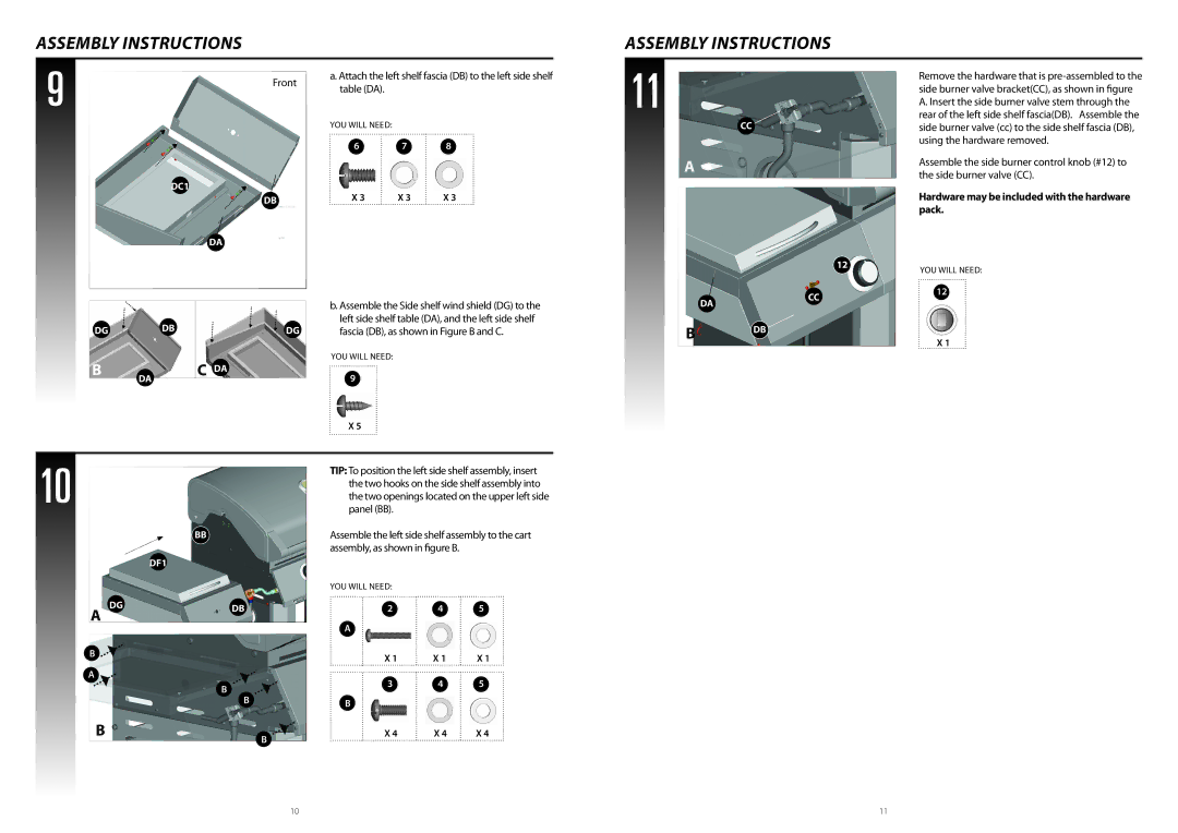
a. Attach the left shelf fascia (DB) to the left side shelf table (DA).
YOU WILL NEED:
6 7 8
11
CC![]()
Remove the hardware that is
DC1
DB
X 3 | X 3 | X 3 |
A
Assemble the side burner control knob (#12) to the side burner valve (CC).
Hardware may be included with the hardware pack.
DA
b. Assemble the Side shelf wind shield (DG) to the |
left side shelf table (DA), and the left side shelf |
DA
12
CC
YOU WILL NEED:
12
DG | DB | DG | fascia (DB), as shown in Figure B and C. | |
B |
| C DA | YOU WILL NEED: | |
DA | 9 | |||
|
|
X 5
BDB
X 1
10
|
| BB |
|
| DF1 |
A | DG | DB |
| ||
|
|
B ![]()
TIP: To position the left side shelf assembly, insert the two hooks on the side shelf assembly into the two openings located on the upper left side panel (BB).
Assemble the left side shelf assembly to the cart assembly, as shown in figure B.
YOU WILL NEED:
2 4 5
A
X 1 | X 1 | X 1 |
A*![]()
B
B
B
B
3 4 5
B
X 4 | X 4 | X 4 |
10 | 11 |
