MANUAL_CVAMPS-REV-B1.qxd:Originator: M. Schlazer Size: 8.5 x 11 7/30/08 11:34 AM Page 5
WARRANTY & RETURN POLICY
Who’s covered by this warranty?
Cerwin-Vega’s Limited Warranty on professional audio products extends only to the original purchaser as evidenced by the original Bill of Sale and only for the products purchased from authorized Cerwin-Vega dealers. Ten words of advice: retain the original bill of sale in a safe place!
What’s covered by this warranty?
Cerwin-Vega warrants that all new professional audio products shall be free from defects in material and workmanship, under normal and proper use. During the warranty period, Cerwin-Vega agrees to repair or replace (at our option) all such defective parts at no charge for labor or materials.
What’s Not covered by this warranty?
This Limited Warranty does not apply to defective equipment that: has been altered or repaired by other than factory approved proce- dures; has been subjected to negligence, misuse or accident; has been damaged by improper line voltage; had its serial number or any part of it altered, defaced, or removed; or has been used in a way that is contrary to Cerwin-Vega’s written instructions. Except as pro- vided by statute, this Limited Warranty does not cover losses, consequential or otherwise, resulting from the improper use of, or inabili- ty to operate, any Cerwin-Vega product.
How long Does the warranty Extend?
Cerwin-Vega’s Limited Warranty extends for a period of (5 ) years for all non-powered speaker systems and related components and (3)
REAR PANEL CONTROLS
years for all stand-alone power amplifiers and related components from date of purchase as shown on the original Bill of Sale. The war- ranty period will be extended if the warranty repairs have not been performed due to delays caused by circumstances beyond the con- trol of the original purchaser, or if the warranty repairs did not remedy the defect and the original purchaser notifies Cerwin-Vega or the original dealer or an Authorized Cerwin-Vega Service Center of the failure of the repairs within 30 days after they were completed.
How Do you get warranty Service?
In order to obtain warranty service, contact your original dealer or distributor, or an Authorized Cerwin-Vega Service Center. If, for some reason, you have trouble locating a service representative, contact Cerwin-Vega’s Customer Service Department for assistance: Cerwin-Vega! Customer Service Dept.
P.O. Box 816667
Hollywood, FL 33081
In some cases, the Customer Service Department can solve a service problem without any return of equipment to Cerwin-Vega, there- |
by avoiding transit delays. | Fax: 954.316.1590. |
Phone: 954.316.1500 option 5 |
E-mail: info@cerwin-vega.com | |
Now, what if the product must be returned?
If the Customer Service Department determines that the equipment must be returned to Cerwin-Vega for service, a Return Authorization will be issued, and the defective merchandise may be shipped directly to the above address freight prepaid, along with a copy of both the Return Authorization and the original Bill of Sale. The product will be repaired or replaced (at our option) and returned to the original purchaser. Only the return postage will be paid by Cerwin-Vega. Cerwin-Vega will not be responsible for damage occurring in shipment from the original purchaser or due to improper packing materials. Remember to pack all equipment carefully and in the original carton if possible. Additional charges may be added if new packing materials are required for return shipment. SAVE YOUR ORIGINAL PACKING MATERIALS!
Other remedies under the law
The exercise of any of the provisions under the Limited Warranty does not affect the protections or remedies of the original purchaser under other laws. If you have additional questions about service, write or call the Customer Service Department. This Limited Warranty applies to all Cerwin-Vega Professional products, and supersedes all previous warranty statements. Cerwin-Vega reserves the right to make changes in product design and specifications at any time.
EXCEPT AS PROVIDED HEREIN AND BY APPLICABLE LAW, CERWIN-VEGA MAKES NO ADDITIONAL REPRESENTATION or WAR-
RANTY OF ANY NATURE WHATSOEVER, EXPRESSED OR IMPLIED, AS TO THE EQUIPMENT, INCLUDING BUT NOT LIMITED TO, THE MERCHANTABILITY, FITNESS FOR A PARTICULAR PURPOSE, DESIGN CONDITION OR WORKMANSHIP OF THE EQUIP- MENT, OR THE QUALITY OF THE MATERIAL INCLUDED THEREIN, THIS LIMITED WARRANTY CONSTITUTES THE SOLE AND ENTIRE AGREEMENT BETWEEN CERWIN-VEGA AND THE ORIGINAL PURCHASER
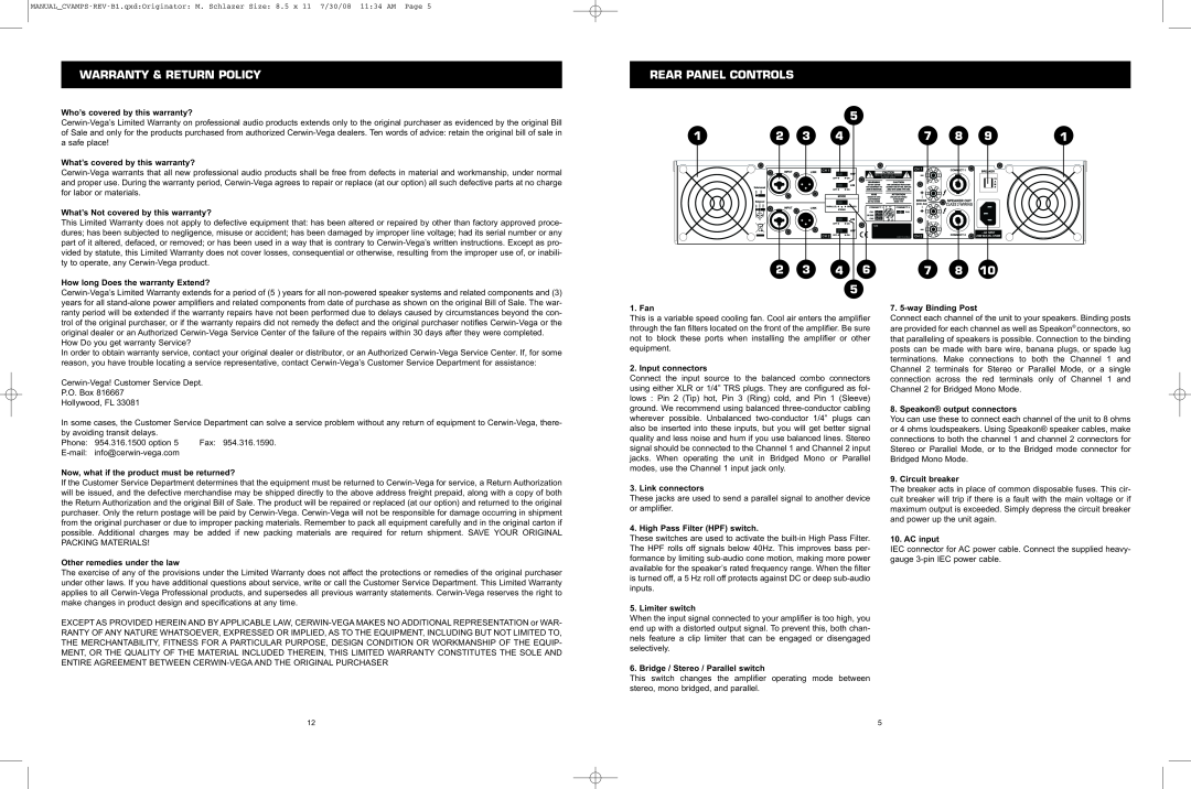
1. Fan
This is a variable speed cooling fan. Cool air enters the amplifier through the fan filters located on the front of the amplifier. Be sure not to block these ports when installing the amplifier or other equipment.
2. Input connectors
Connect the input source to the balanced combo connectors using either XLR or 1/4” TRS plugs. They are configured as fol- lows : Pin 2 (Tip) hot, Pin 3 (Ring) cold, and Pin 1 (Sleeve) ground. We recommend using balanced three-conductor cabling wherever possible. Unbalanced two-conductor 1/4” plugs can also be inserted into these inputs, but you will get better signal quality and less noise and hum if you use balanced lines. Stereo signal should be connected to the Channel 1 and Channel 2 input jacks. When operating the unit in Bridged Mono or Parallel modes, use the Channel 1 input jack only.
3. Link connectors
These jacks are used to send a parallel signal to another device or amplifier.
4. High Pass Filter (HPF) switch.
These switches are used to activate the built-in High Pass Filter. The HPF rolls off signals below 40Hz. This improves bass per- formance by limiting sub-audio cone motion, making more power available for the speaker’s rated frequency range. When the filter is turned off, a 5 Hz roll off protects against DC or deep sub-audio inputs.
5. Limiter switch
When the input signal connected to your amplifier is too high, you end up with a distorted output signal. To prevent this, both chan- nels feature a clip limiter that can be engaged or disengaged selectively.
6. Bridge / Stereo / Parallel switch
This switch changes the amplifier operating mode between stereo, mono bridged, and parallel.
7. 5-way Binding Post
Connect each channel of the unit to your speakers. Binding posts are provided for each channel as well as Speakon® connectors, so that paralleling of speakers is possible. Connection to the binding posts can be made with bare wire, banana plugs, or spade lug terminations. Make connections to both the Channel 1 and Channel 2 terminals for Stereo or Parallel Mode, or a single connection across the red terminals only of Channel 1 and Channel 2 for Bridged Mono Mode.
8. Speakon® output connectors
You can use these to connect each channel of the unit to 8 ohms or 4 ohms loudspeakers. Using Speakon® speaker cables, make connections to both the channel 1 and channel 2 connectors for Stereo or Parallel Mode, or to the Bridged mode connector for Bridged Mono Mode.
9. Circuit breaker
The breaker acts in place of common disposable fuses. This cir- cuit breaker will trip if there is a fault with the main voltage or if maximum output is exceeded. Simply depress the circuit breaker and power up the unit again.
10. AC input
IEC connector for AC power cable. Connect the supplied heavy- gauge 3-pin IEC power cable.