SM-LW12 specifications
The Cerwin-Vega SM-LW12 is a powerful and versatile subwoofer that stands out in the realms of professional audio and home theater systems. Designed for those who demand impactful bass without compromising on sound clarity, the SM-LW12 incorporates advanced technologies that enhance its performance, making it a favorite among audiophiles and sound engineers alike.One of the key features of the SM-LW12 is its impressive 12-inch bass driver, which is engineered to deliver deep, resonant lows. This driver is constructed with high-quality materials that ensure durability and longevity, while also optimizing sound output. The subwoofer’s efficient design allows it to handle high power levels, producing tight and punchy bass that can fill large spaces.
The SM-LW12 utilizes a robust 800-watt peak power handling capability. This high power rating ensures that the subwoofer can produce dynamic sound even at high volumes, making it perfect for both live sound applications and home environments. Moreover, the subwoofer’s frequency response ranges from 28 Hz to 200 Hz, allowing it to reproduce the lowest frequencies without distortion, providing an immersive listening experience.
Cerwin-Vega has incorporated advanced acoustic technologies into the SM-LW12. The subwoofer features a built-in high-pass filter, which allows users to customize the sound output to suit their specific audio needs. This feature is particularly beneficial in multi-speaker setups, where integration with other components is crucial for a seamless audio experience.
Another notable characteristic of the SM-LW12 is its efficient heat dissipation capabilities. It is designed with a ventilated enclosure that not only enhances overall sound clarity but also prevents overheating during prolonged use. This ensures consistent performance and reliability, even in demanding situations.
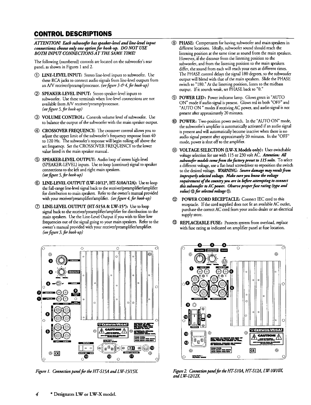
Connectivity options on the SM-LW12 are comprehensive, featuring both XLR and 1/4-inch inputs. This flexibility allows the subwoofer to integrate easily into various audio setups, whether in a professional studio, live sound environment, or home theater system.
In summary, the Cerwin-Vega SM-LW12 is a high-performance subwoofer that delivers powerful bass with clarity and precision. Its durable construction, high power handling, advanced technologies, and versatile connectivity options make it an excellent choice for anyone seeking to enhance their audio experience. Whether for music production, live events, or home entertainment, the SM-LW12 is engineered to impress and elevate sound quality to new heights.

