Cerwin-Vega 
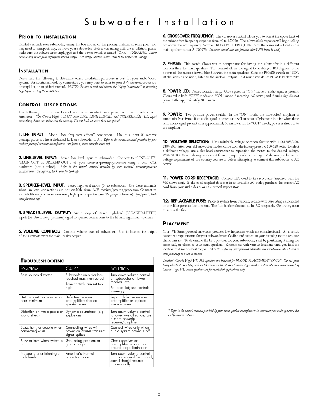
VE-5C, VE-15 S u b w o o f e r I n s t a l l a t i o n, tRoUblEShootIng, plaCEMEnt

Models: VE-8 VE-28S V E - 5 M VE-12 VE-15 VE-5C

1 24
Download 24 pages 58.51 Kb
Page 6
Image 6
S u b w o o f e r I n s t a l l a t i o n

S u b w o o f e r I n s t a l l a t i o n

pRIoR to InStallatIon

Carefully unpack your subwoofer, saving the box and all of the packing material; at some point you may need to transport, ship, or move your subwoofer. Before continuing with the installation, please make sure the subwoofer is unplugged and the power switch is turned “OFF.” WaRNING: Severe damage may result from improperly selected voltage. Set voltage selection switch, (10) to the proper aC voltage.

InStallatIon

Please read the following to determine which installation procedure is best for your audio/video system. For additional hook-up connections, you may want to refer to your A/V receiver, processor, preamplifier, or amplifier’s manual. NOTE: Be sure to read and observe the “Safety Instructions” on preceding page before starting the installation.

ContRol DESCRIptIonS

The following controls are located on the subwoofer’s rear panel, as shown (back cover). Attention! The Cerwin-Vega!VE-28S have LFE, LINE-LEVEL, and SPEaKER-LEVEL input connections; choose one option only for hook-up. Do not hook up more than one option!

1.lfE InpUt: Mono “low frequency effects” connection. Use this input if receiver preamp/processor has a dedicated LFE or subwoofer OUT. Refer to the owner’s manual provided by your receiver/preamp/processor manufacturer. (see figure 1, back cover for hook-up)

2.lInE-lEVEl InpUt: Stereo low level input to subwoofer. Connect to “LINE-OUT”, “MAIN-OUT or PREAMP-OUT”, of your receiver/preamp/processor using a dual RCA patchcord (not supplied). Refer to the owner’s manual provided by your receiver/ preamp/processor manufacturer. (see figure 2, back cover for hook-up)

3.SpEakER-lEVEl InpUt: Stereo high-level inputs (3) to subwoofer. Use these terminals when line-level connections are not available from A/V receiver/preamp/processor. Connect to SPEAKER outputs on receiver using high quality speaker wire (16-gauge or heavier). (see figure 3, back cover for hook-up)

4.SpEakER-lEVEl oUtpUt: Audio loop of stereo high-level (SPEAKER-LEVEL) inputs (3). Use to loop (continue) signal to speaker connections to the left and right main speakers.

5.VolUME ContRol: Controls volume level of subwoofer. Use to balance the output of the subwoofer with the main speaker output.

tRoUblEShootIng

Symptom

CauSe

Solution

Bass sounds distorted

Subwoofer amplifier has

turn down volume control


reached maximum output

on subwoofer or lower


tone controls are set too

receiver level


Set bass flat; use controls


high


sparingly

Distortion with volume control

Defective receiver or

Repair defective receiver,

near minimum

preamplifier; shorted

preamplifier or replace


speaker wires

speaker wires


Distortion on music peaks or

Dynamic soundtrack (e.g.,

turn down volume control

sound effects

explosions)

to lower overall range; use


a more powerful


receiver/amplifier

Buzz, hum, or crackle when

Connecting wires with

Connect wires only when

connecting wires

power on causes transient

audio system power is off


signal spikes


Buzz or hum when system is

Grounding problem or

Check receiver or

on

ground loop

preamplifier manual for


ground loop elimination

no sound after listening at

amplifier’s thermal

turn down volume control

high levels

protection is on

and allow amplifier to cool;


sound should resume


automatically

6.CRoSSoVER fREQUEnCy: The crossover control allows you to adjust the upper limit of the subwoofer’s frequency response from 40 to 120 Hz. The subwoofer’s response will begin rolling off above the set frequency. Set the CROSSOVER FREQUENCY to the lower value listed in the main speaker manual.* (NOTE: Crossover control does not function when LFE input is used.)

7.phaSE: This switch allows you to compensate for having the subwoofer in a different location than the main speakers. This control allows the signal to be delayed 180 degrees so the output of the subwoofer will blend in with the main speakers. Slide the PHASE switch to “180”. At the listening position, listen to the midbass output. If it sounds weak, set PHASE back to “0.”

8.powER lED: Power indicator lamp. Glows green in “ON” mode if audio signal is present. Glows red in both “OFF” mode and “ON ” mode if receiving AC power, and if audio signal is not present after approximately 30 minutes.

9.powER: Two-position power switch. In the “ON” mode, the subwoofer’s amplifier is automatically activated if an audio signal is present and will automatically become inactive when there is no audio signal present after approximately 30 minutes. In the “OFF” mode, power is shut off to the amplifier.

10.VoltagE SElECtIon: User-switchable voltage selection for use with 110-120V/220-

240V AC. Attention: All subwoofer models come from the factory preset to 110-120 volts. To select a different voltage, use a flat head screwdriver to reposition the switch to the desired voltage. WARNING: Severe damage may result from improperly selected voltage. Make sure you know the voltage requirement of the country you are in before attempting to connect this subwoofer to AC power.

11.powER CoRD RECEptaClE: Connect IEC cord to this receptacle (supplied with the VE subwoofer). If the cord supplied does not fit an available AC outlet, purchase the correct AC cord from your audio dealer or an electrical supply store.

12.REplaCEablE fUSE: Protects system from overload, replace with fuse rating as indicated on amplifier panel at fuse location. The fuse holder is located at the AC receptacle. Gently pry open to access the fuse.

plaCEMEnt

Your VE Series powered subwoofer produces low frequencies which are omnidirectional. As a result, placement requirements for your subwoofer are flexible and subject to your listening room’s acoustic characteristics. To determine the best position for your subwoofer, start by positioning it along the same wall, or plane, as your main speakers. Experiment with various locations until you find the location that sounds best to you. NOTE: Typically, your powered subwoofer will sound louder when placed in close proximity to walls or corners.

Caution! Cerwin-Vega! VE-28S speakers are intended for FLOOR PLaCEMENT ONLy! Do not place heavy objects of any type, such as televisions on top of any Cerwin-Vega! speaker unless otherwise recommended by Cerwin-Vega! VE Series speakers are for residential applications only.

*Refer to the owner’s manual provided by your main speaker manufacturer to determine your main speaker’s low end frequency response.

2

Page 6
Image 6
Cerwin-Vega VE-5C, VE-15, VE-12, V E - 5 M, VE-28S, VE-8 S u b w o o f e r I n s t a l l a t i o n, tRoUblEShootIng, plaCEMEnt