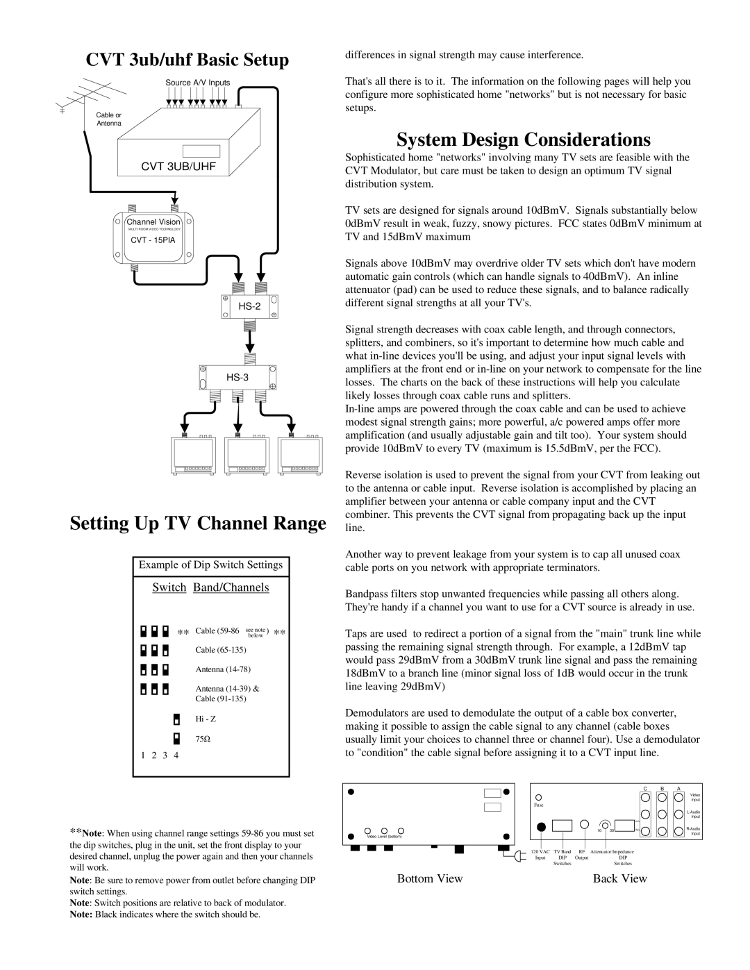
CVT 3ub/uhf Basic Setup
Source A/V Inputs
Cable or
Antenna
CVT 3UB/UHF
Channel Vision
MULTI ROOM VIDEO TECHNOLOGY
CVT - 15PIA
Setting Up TV Channel Range
Example of Dip Switch Settings
Switch Band/Channels
** Cable
Cable
Antenna
Antenna
Cable
Hi - Z
75Ω
1 2 3 4
differences in signal strength may cause interference.
That's all there is to it. The information on the following pages will help you configure more sophisticated home "networks" but is not necessary for basic setups.
System Design Considerations
Sophisticated home "networks" involving many TV sets are feasible with the CVT Modulator, but care must be taken to design an optimum TV signal distribution system.
TV sets are designed for signals around 10dBmV. Signals substantially below 0dBmV result in weak, fuzzy, snowy pictures. FCC states 0dBmV minimum at TV and 15dBmV maximum
Signals above 10dBmV may overdrive older TV sets which don't have modern automatic gain controls (which can handle signals to 40dBmV). An inline attenuator (pad) can be used to reduce these signals, and to balance radically different signal strengths at all your TV's.
Signal strength decreases with coax cable length, and through connectors, splitters, and combiners, so it's important to determine how much cable and what
Reverse isolation is used to prevent the signal from your CVT from leaking out to the antenna or cable input. Reverse isolation is accomplished by placing an amplifier between your antenna or cable company input and the CVT combiner. This prevents the CVT signal from propagating back up the input line.
Another way to prevent leakage from your system is to cap all unused coax cable ports on you network with appropriate terminators.
Bandpass filters stop unwanted frequencies while passing all others along. They're handy if a channel you want to use for a CVT source is already in use.
Taps are used to redirect a portion of a signal from the "main" trunk line while passing the remaining signal strength through. For example, a 12dBmV tap would pass 29dBmV from a 30dBmV trunk line signal and pass the remaining 18dBmV to a branch line (minor signal loss of 1dB would occur in the trunk line leaving 29dBmV)
Demodulators are used to demodulate the output of a cable box converter, making it possible to assign the cable signal to any channel (cable boxes usually limit your choices to channel three or channel four). Use a demodulator to "condition" the cable signal before assigning it to a CVT input line.
**Note: When using channel range settings
Note: Be sure to remove power from outlet before changing DIP switch settings.
Note: Switch positions are relative to back of modulator.
Note: Black indicates where the switch should be.
Video Level (bottom)
Bottom View
|
|
|
|
| C | B | A |
|
|
|
|
|
|
| Video |
|
|
|
|
|
|
| Input |
Fuse |
|
|
|
|
|
|
|
|
|
|
|
|
|
| |
|
|
|
|
|
|
| Input |
|
|
|
|
| 1KΩ |
|
|
|
|
| 10 | 30 | 75Ω |
| |
|
|
|
|
| Input | ||
|
|
|
|
|
|
| |
120 VAC | TV Band | RF | Attenuator Impedance |
|
|
| |
Input | DIP | Output |
| DIP |
|
|
|
| Switches |
|
| Switches |
|
|
|
Back View