ASSEMBLY
Tools required for assembly:
Phillips Screwdriver (Not Supplied); Small Adjustable Wrench (Not Supplied)
1
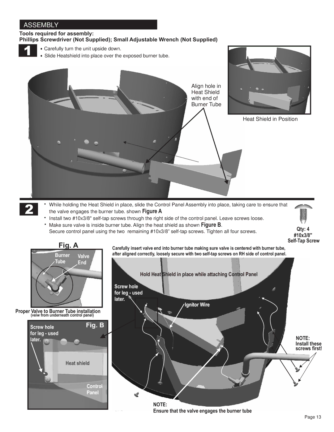
•Carefully turn the unit upside down.
•Slide Heatshield into place over the exposed burner tube.
Align hole in Heat Shield with end of Burner Tube
Heat Shield in Position
| • | While holding the Heat Shield in place, slide the Control Panel Assembly into place, taking care to ensure that | |
2 | |||
| the valve engages the burner tube. shown Figure A |
•Install two #10x3/8"
•Make sure valve is inside burner tube. Align the heat shield as shown Figure B.
Secure control panel using the two remaining #10x3/8”
Qty: 4
#10x3/8"
Fig. A
Burner Valve
Tube End
Proper Valve to Burner Tube installation
(veiw from underneath control panel)
Screw hole | Fig. B |
for leg - used |
|
later. |
|
Heat shield
Control
Panel
Carefully insert valve end into burner tube making sure valve is centered with burner tube, after aligned correctly, loosely secure with two
Hold Heat Shield in place while attaching Control Panel
Screw hole for leg - used later.
Ignitor Wire
NOTE:
Ensure that the valve engages the burner tube
NOTE:
Install these screws first!
Page 13
