11
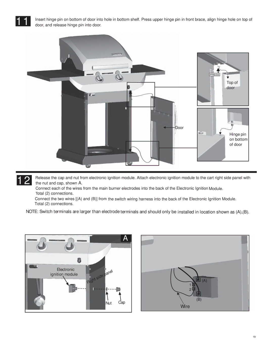
Insert hinge pin on bottom of door into hole in bottom shelf. Press upper hinge pin in front brace, align hinge hole on top of door, and release hinge pin into door.
![]() Door
Door
PRESS
Top of door
Hinge pin on bottom of door
12
Release the cap and nut from electronic ignition module. Attach electronic ignition module to the cart right side panel with the nut and cap, shown A.
Connect each of the wires from the main burner electrodes into the back of the Electronic Ignition Module. Total (2) connections.
Connect the two wires [(A) and (B)] from the switch wiring harness into the back of the Electronic Ignition Module. Total (2) connections.
NOTE: Switch terminals are larger than electrode terminals and should only be installed in location shown as (A),(B).
A
Electronic ignition module
Nut Cap
![]()
![]()
![]() (A)
(A)
1![]()
2![]()
(B)
Wire
19