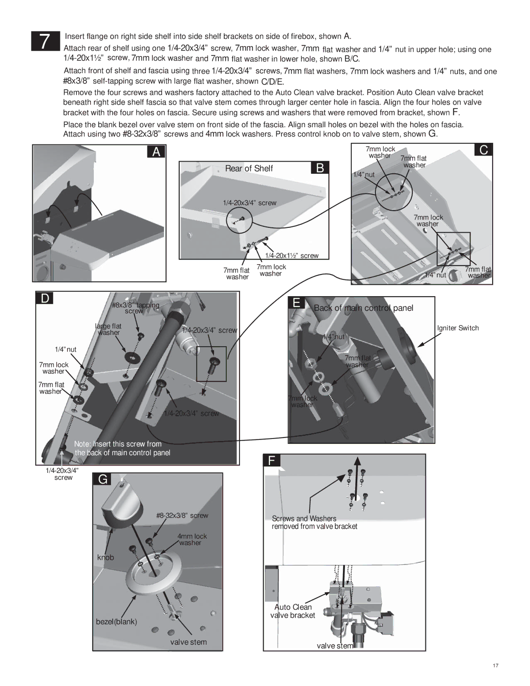
| Insert flange on right side shelf into side shelf brackets on side of firebox, shown A. | |
7 | ||
Attach rear of shelf using one | ||
| ||
|
Attach front of shelf and fascia using three
Remove the four screws and washers factory attached to the Auto Clean valve bracket. Position Auto Clean valve bracket beneath right side shelf fascia so that valve stem comes through larger center hole in fascia. Align the four holes on valve bracket with the four holes on fascia. Secure using screws and washers that were removed from bracket, shown F.
Place the blank bezel over valve stem on front side of the fascia. Align small holes on bezel with the holes on fascia. Attach using two
A
|
| |
Rear of Shelf | B | |
|
![]()
7mm flat 7mm lock washer washer
|
|
|
|
7mm lock |
| C |
|
washer | 7mm flat |
|
|
|
| ||
1/4”nut | washer |
|
|
|
|
|
7mm lock washer
7mm flat
1/4”nut washer
D
#8x3/8” tapping screw
E Back of main control panel
large flat | |
washer |
1/4”nut
7mm lock ![]() washer
washer
7mm flat ![]() washer
washer![]()
Note: Insert this screw from the back of main control panel
screw G
4mm lock ![]() washer
washer
knob
bezel(blank)
valve stem
Igniter Switch
1/4”nut
7mm flat washer
7mm lock washer
![]() F
F
Screws and Washers removed from valve bracket
Auto Clean valve bracket
valve stem
17