
463270311 specifications
The Char-Broil 463270311 is a popular gas grill that combines convenience, efficiency, and impressive performance, making it a favorite among outdoor cooking enthusiasts. This model is designed to provide a seamless grilling experience, whether you're preparing a quick weeknight meal or hosting a weekend barbecue.One of the standout features of the Char-Broil 463270311 is its innovative TRU-Infrared cooking technology. This unique system ensures even heat distribution across the cooking surface, eliminating cold and hot spots that can lead to uneven cooking. By using infrared heat, this grill also minimizes flare-ups, allowing for a more controlled cooking process. This technology not only enhances the flavor of your food but also contributes to quicker cooking times.
With a primary cooking area of 450 square inches, the Char-Broil 463270311 offers ample space to grill multiple items simultaneously. It comes equipped with four main burners, each producing up to 10,000 BTUs, providing a total of 40,000 BTUs of cooking power. This robust burner system allows for versatile cooking options, accommodating everything from searing steaks to gently roasting vegetables.
The grill features a porcelain-coated cast iron cooking surface, which provides excellent heat retention and is easy to clean. Additionally, the warming rack adds an extra 150 square inches of space, making it ideal for keeping cooked food warm or toasting buns while you finish grilling the main dishes.
Durability is another key characteristic of the Char-Broil 463270311. The grill is constructed with a sturdy stainless steel body, ensuring it can withstand the elements and maintain its appearance over time. The lid features a built-in temperature gauge, making it easy to monitor cooking temperatures without lifting the lid.
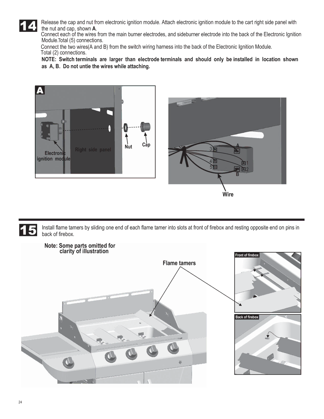
For added convenience, the grill is equipped with an electronic ignition system, allowing for quick and reliable start-ups with the push of a button. The side shelves provide extra workspace for food preparation and include tool hooks for easy access to grilling tools. Additionally, the grill is mounted on wheels, making it easy to move around your patio or backyard.
Overall, the Char-Broil 463270311 combines practicality with performance, making it an excellent choice for both beginner and seasoned grillers. With its advanced cooking technology, spacious cooking area, and durable construction, this grill ensures that outdoor cooking is a pleasurable and efficient experience.