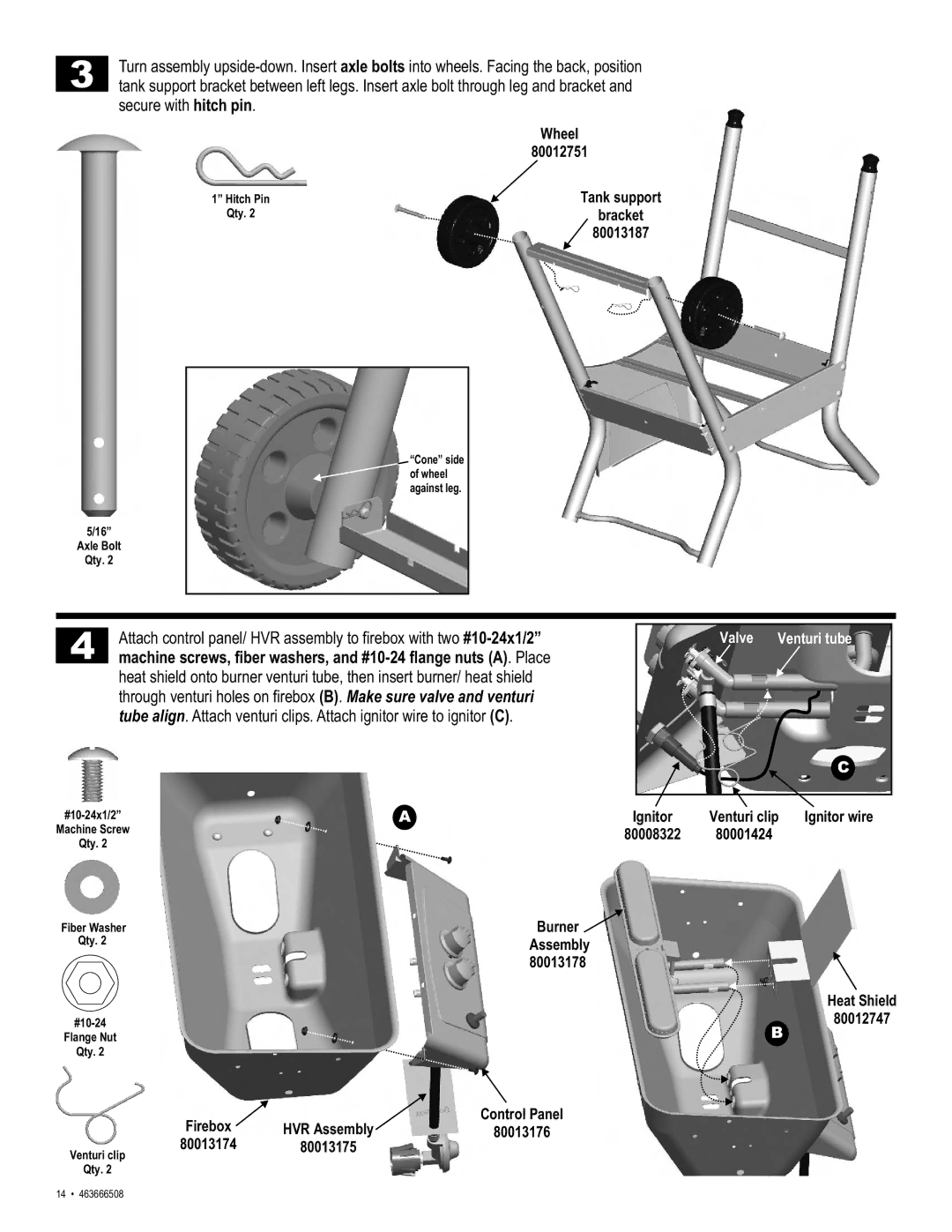
3
Turn assembly
| Wheel |
| 80012751 |
1” Hitch Pin | Tank support |
Qty. 2 | bracket |
| 80013187 |
5/16”
Axle Bolt
Qty. 2
![]() “Cone” side
“Cone” side
of wheel
against leg.
4
Attach control panel/ HVR assembly to firebox with two
machine screws, fiber washers, and
heat shield onto burner venturi tube, then insert burner/ heat shield through venturi holes on firebox (B). Make sure valve and venturi tube align. Attach venturi clips. Attach ignitor wire to ignitor (C).
Valve | Venturi tube |
C
A | Ignitor | Venturi clip | Ignitor wire | |
Machine Screw |
| 80008322 | 80001424 |
|
Qty. 2 |
|
|
|
|
Fiber Washer |
| Burner |
|
|
Qty. 2 |
| Assembly |
|
|
|
| 80013178 |
|
|
|
|
|
| Heat Shield |
|
| B | 80012747 | |
Flange Nut |
|
|
| |
Qty. 2 |
|
|
|
|
Firebox | HVR Assembly | Control Panel |
|
|
80013176 |
|
| ||
80013174 | 80013175 |
|
|
|
Venturi clip |
|
|
|
|
Qty. 2 |
|
|
|
|
14 • 463666508