Setup
Dipswitch Settings
A
| Sets the total width one driver will display. The width can be described in either number |
JP1 | of panels or pixel resolution. Possible widths include 1 to 6 panels or 16 to 96 horizontal |
| pixels. |
| Sets the starting vertical line from which this driver will begin to display video. Remember |
JP2 | that a matrix may consist of multiple sections across, so in order to display video |
| correctly you will need to set the starting address for each section handled by a driver. |
JP1 Dipswitch
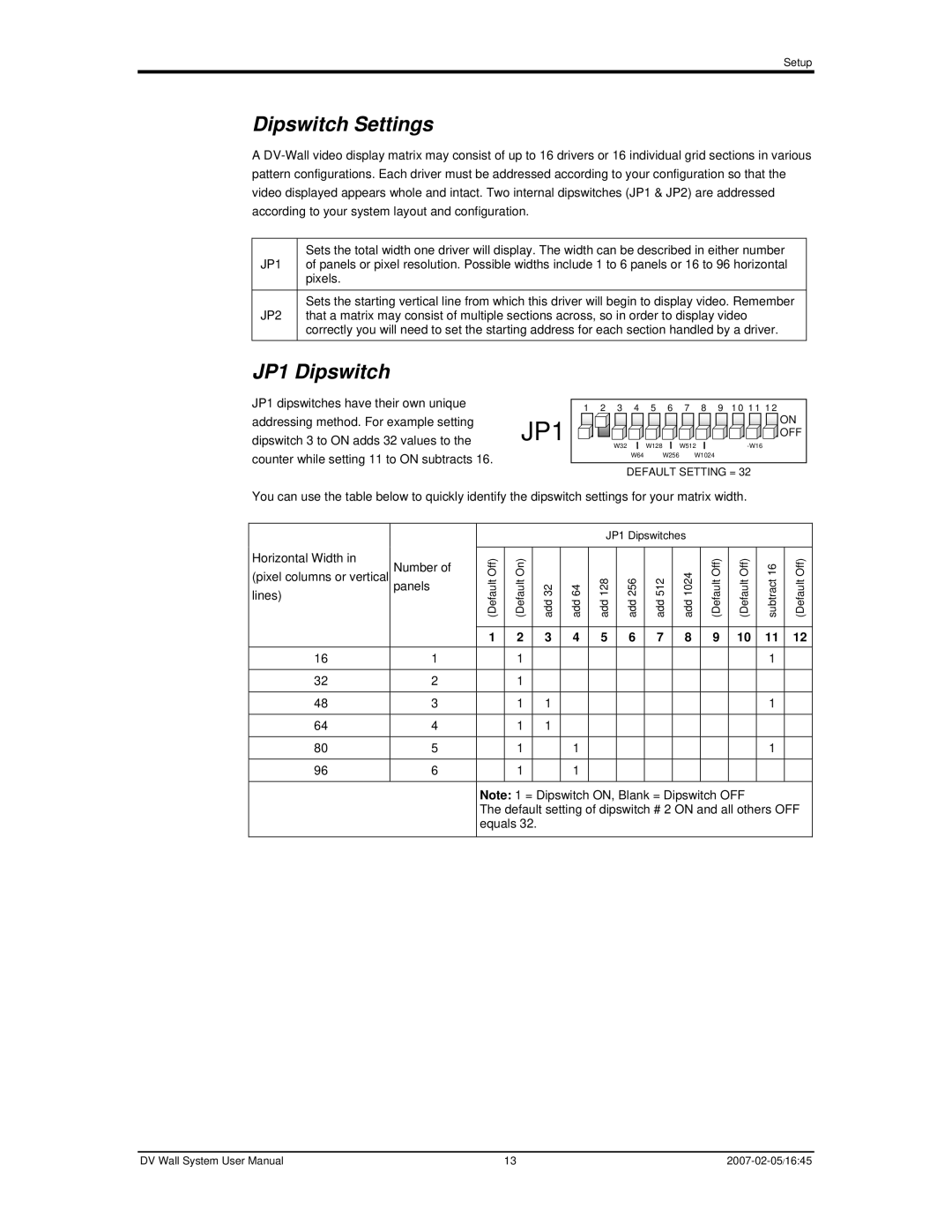
JP1 dipswitches have their own unique addressing method. For example setting dipswitch 3 to ON adds 32 values to the counter while setting 11 to ON subtracts 16.
1 | 2 | 3 | 4 | 5 | 6 | 7 | 8 | 9 10 11 12 |
JP1 |
|
|
|
|
|
|
| ON |
|
|
|
|
|
|
| OFF | |
| W32 |
| W128 |
| W512 | |||
|
|
| W64 |
| W256 |
| W1024 |
|
DEFAULT SETTING = 32
You can use the table below to quickly identify the dipswitch settings for your matrix width.
JP1 Dipswitches
Horizontal Width in | Number of | (Default Off) | (Default On) |
|
|
|
|
|
|
| (Default Off) | (Default Off) | subtract 16 | (Default Off) |
(pixel columns or vertical |
|
|
| add 128 | add 256 | add 512 | add 1024 | |||||||
lines) | panels |
| add 32 | add 64 | ||||||||||
|
| |||||||||||||
|
|
| ||||||||||||
|
|
|
|
|
|
|
|
|
|
|
|
|
|
|
|
| 1 | 2 |
| 3 | 4 | 5 | 6 | 7 | 8 | 9 | 10 | 11 | 12 |
16 | 1 |
| 1 |
|
|
|
|
|
|
|
|
| 1 |
|
|
|
|
|
|
|
|
|
|
|
|
|
|
|
|
32 | 2 |
| 1 |
|
|
|
|
|
|
|
|
|
|
|
|
|
|
|
|
|
|
|
|
|
|
|
|
|
|
48 | 3 |
| 1 |
| 1 |
|
|
|
|
|
|
| 1 |
|
|
|
|
|
|
|
|
|
|
|
|
|
|
|
|
64 | 4 |
| 1 |
| 1 |
|
|
|
|
|
|
|
|
|
|
|
|
|
|
|
|
|
|
|
|
|
|
|
|
80 | 5 |
| 1 |
|
| 1 |
|
|
|
|
|
| 1 |
|
|
|
|
|
|
|
|
|
|
|
|
|
|
|
|
96 | 6 |
| 1 |
|
| 1 |
|
|
|
|
|
|
|
|
|
|
|
|
|
|
|
|
|
|
|
|
|
| |
|
| Note: 1 = Dipswitch ON, Blank = Dipswitch OFF |
|
| ||||||||||
|
| The default setting of dipswitch # 2 ON and all others OFF | ||||||||||||
|
| equals 32. |
|
|
|
|
|
|
|
|
|
| ||
DV Wall System User Manual | 13 |