Setup
Transmitter Card
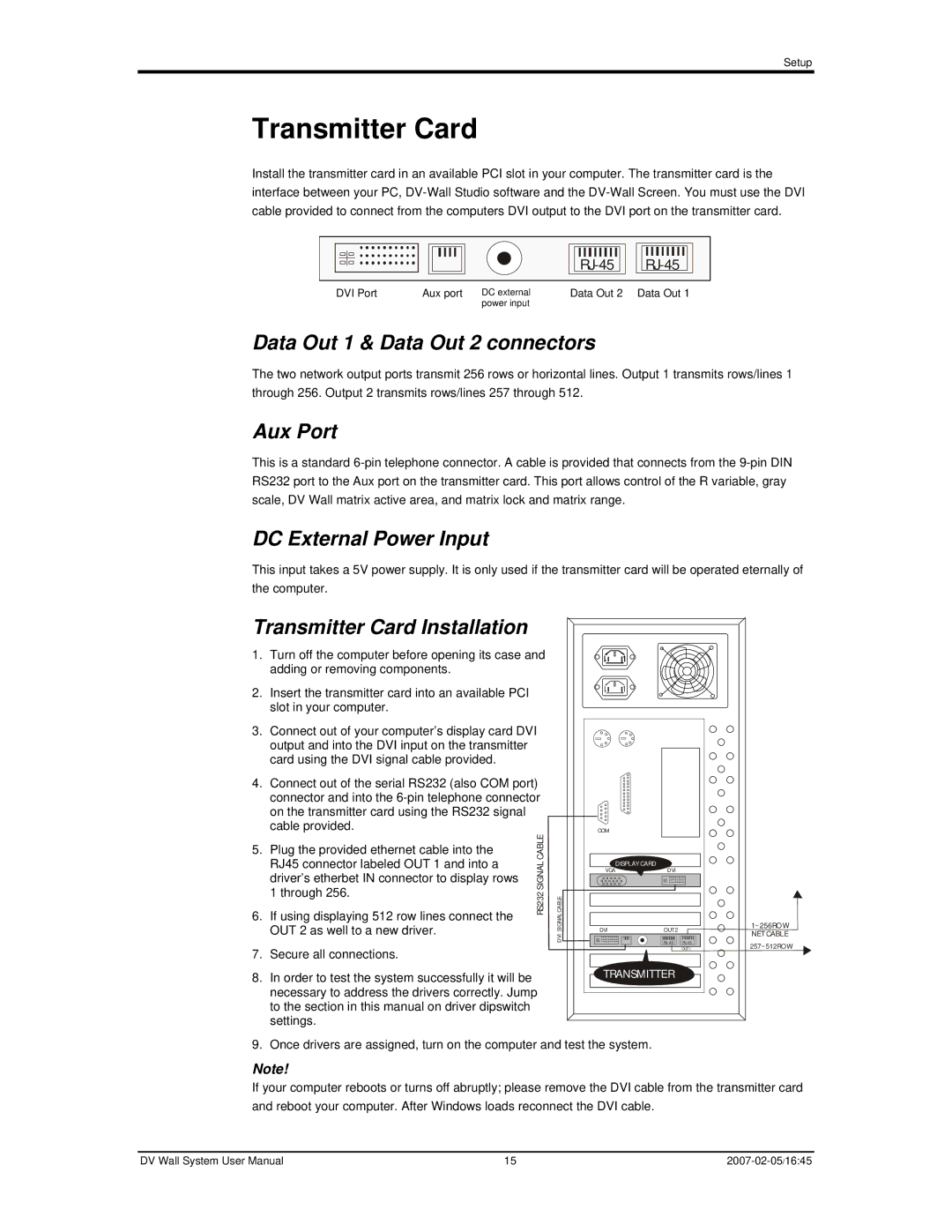
Install the transmitter card in an available PCI slot in your computer. The transmitter card is the interface between your PC,
|
| ||
DVI Port | Aux port DC external | Data Out 2 | Data Out 1 |
| power input |
|
|
Data Out 1 & Data Out 2 connectors
The two network output ports transmit 256 rows or horizontal lines. Output 1 transmits rows/lines 1 through 256. Output 2 transmits rows/lines 257 through 512.
Aux Port
This is a standard
DC External Power Input
This input takes a 5V power supply. It is only used if the transmitter card will be operated eternally of the computer.
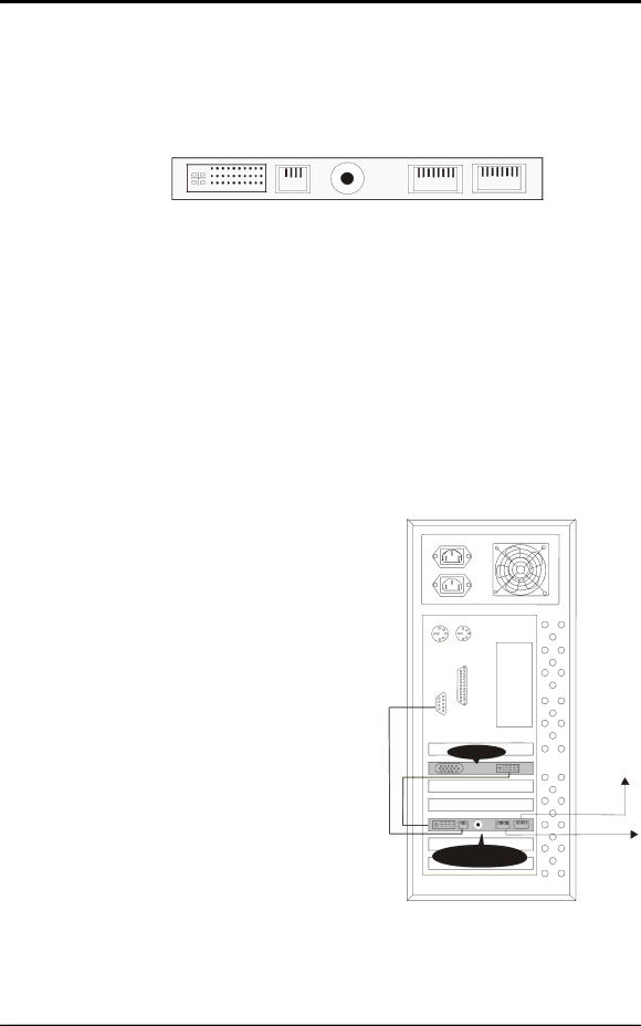
Transmitter Card Installation
1. | Turn off the computer before opening its case and |
| |
| adding or removing components. |
|
|
2. | Insert the transmitter card into an available PCI |
|
|
| slot in your computer. |
|
|
3. | Connect out of your computer’s display card DVI |
| |
| output and into the DVI input on the transmitter |
|
|
| card using the DVI signal cable provided. |
|
|
4. | Connect out of the serial RS232 (also COM port) |
| |
| connector and into the |
| |
| on the transmitter card using the RS232 signal |
|
|
| cable provided. | CABLE |
|
5. | Plug the provided ethernet cable into the |
| |
| RJ45 connector labeled OUT 1 and into a | SIGNAL |
|
| driver’s etherbet IN connector to display rows |
| |
|
|
| |
| 1 through 256. | RS232 | SIGNALCABLE |
6. | If using displaying 512 row lines connect the | ||
| OUT 2 as well to a new driver. |
| DVI |
|
|
| |
7. | Secure all connections. |
|
|
8. | In order to test the system successfully it will be |
|
|
| necessary to address the drivers correctly. Jump |
| |
to the section in this manual on driver dipswitch settings.
COM
DISPLAY CARD
VGADVI
DVI | OUT 2 |
| |
| OUT1 |
TRANSMITTER
1~256ROW NETCABLE
257~512ROW
9. Once drivers are assigned, turn on the computer and test the system.
Note!
If your computer reboots or turns off abruptly; please remove the DVI cable from the transmitter card and reboot your computer. After Windows loads reconnect the DVI cable.
DV Wall System User Manual | 15 |