WATER TANK
(3)
MACHINE
FRAME
FIGURE E
(11)
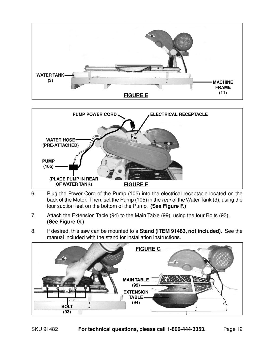
PUMP POWER CORD | ELECTRICAL RECEPTACLE |
WATER HOSE
PUMP
(105)
(PLACE PUMP IN REAR | FIGURE F |
OF WATER TANK) |
6.Plug the Power Cord of the Pump (105) into the electrical receptacle located on the back of the Motor. Then, set the Pump (105) in the rear of the Water Tank (3), using the four suction feet on the bottom of the Pump. (See Figure F.)
7.Attach the Extension Table (94) to the Main Table (99), using the four Bolts (93).
(See Figure G.)
8.If desired, this saw can be mounted to a Stand (ITEM 91483, not included). See the manual included with the stand for installation instructions.
FIGURE G
MAIN TABLE
(99)
EXTENSION
TABLE
(94)
BOLT
(93)
SKU 91482 | For technical questions, please call | Page 12 |