Installation Instructions

MSMVPU/LSMVPU

(R)

5

6

7


(QC) x 4


10


8

9


(QB) x 4


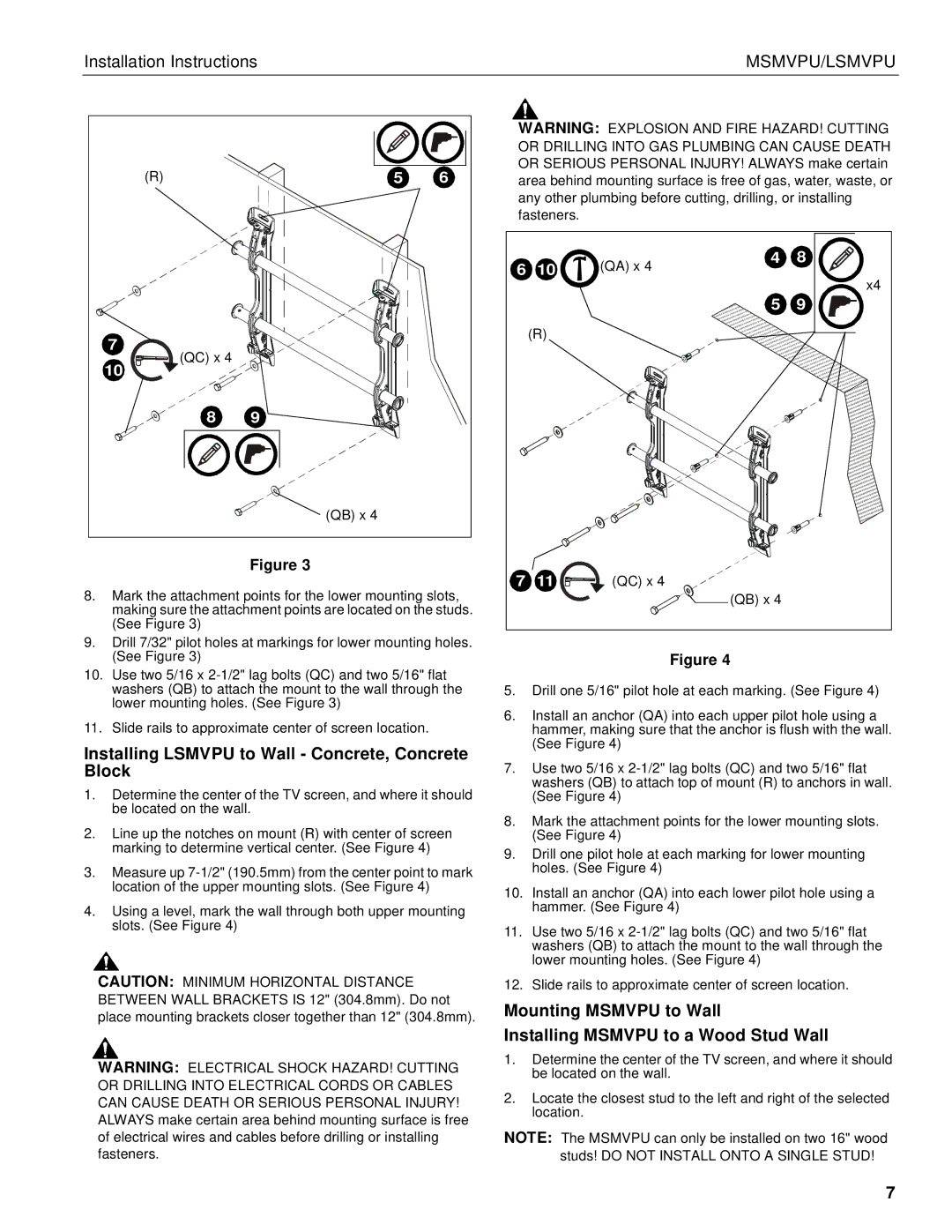
Figure 3

8.Mark the attachment points for the lower mounting slots, making sure the attachment points are located on the studs. (See Figure 3)

9.Drill 7/32" pilot holes at markings for lower mounting holes. (See Figure 3)

10.Use two 5/16 x 2-1/2" lag bolts (QC) and two 5/16" flat washers (QB) to attach the mount to the wall through the lower mounting holes. (See Figure 3)

11.Slide rails to approximate center of screen location.

Installing LSMVPU to Wall - Concrete, Concrete Block

1.Determine the center of the TV screen, and where it should be located on the wall.

2.Line up the notches on mount (R) with center of screen marking to determine vertical center. (See Figure 4)

3.Measure up 7-1/2" (190.5mm) from the center point to mark location of the upper mounting slots. (See Figure 4)

4.Using a level, mark the wall through both upper mounting slots. (See Figure 4)

CAUTION: MINIMUM HORIZONTAL DISTANCE BETWEEN WALL BRACKETS IS 12" (304.8mm). Do not place mounting brackets closer together than 12" (304.8mm).

WARNING: ELECTRICAL SHOCK HAZARD! CUTTING OR DRILLING INTO ELECTRICAL CORDS OR CABLES CAN CAUSE DEATH OR SERIOUS PERSONAL INJURY! ALWAYS make certain area behind mounting surface is free of electrical wires and cables before drilling or installing fasteners.

WARNING: EXPLOSION AND FIRE HAZARD! CUTTING OR DRILLING INTO GAS PLUMBING CAN CAUSE DEATH OR SERIOUS PERSONAL INJURY! ALWAYS make certain area behind mounting surface is free of gas, water, waste, or any other plumbing before cutting, drilling, or installing

fasteners.


6

10

(QA) x 4

4

8


x4


5

9


(R)


7

11

(QC) x 4

(QB) x 4


Figure 4

5.Drill one 5/16" pilot hole at each marking. (See Figure 4)

6.Install an anchor (QA) into each upper pilot hole using a hammer, making sure that the anchor is flush with the wall. (See Figure 4)

7.Use two 5/16 x 2-1/2" lag bolts (QC) and two 5/16" flat washers (QB) to attach top of mount (R) to anchors in wall. (See Figure 4)

8.Mark the attachment points for the lower mounting slots. (See Figure 4)

9.Drill one pilot hole at each marking for lower mounting holes. (See Figure 4)

10.Install an anchor (QA) into each lower pilot hole using a hammer. (See Figure 4)

11.Use two 5/16 x 2-1/2" lag bolts (QC) and two 5/16" flat washers (QB) to attach the mount to the wall through the lower mounting holes. (See Figure 4)

12.Slide rails to approximate center of screen location.

Mounting MSMVPU to Wall

Installing MSMVPU to a Wood Stud Wall

1.Determine the center of the TV screen, and where it should be located on the wall.

2.Locate the closest stud to the left and right of the selected location.

NOTE: The MSMVPU can only be installed on two 16" wood studs! DO NOT INSTALL ONTO A SINGLE STUD!

7

Page 7
Image 7
Chief Manufacturing LSMVPU, MSMVPU installation instructions Installing Lsmvpu to Wall Concrete, Concrete Block, QC x QB x

LSMVPU, MSMVPU specifications

Chief Manufacturing has established itself as a leader in creating innovative mounting solutions with a diverse range of products. Among these, the MSMVPU (Multi-Screen Mount Video Presentation Unit) and LSMVPU (Large Screen Mount Video Presentation Unit) are standout offerings designed for modern audiovisual setups, particularly in educational and corporate environments.

The MSMVPU is engineered to support multiple displays, catering to scenarios where collaborative presentations and visual engagement are critical. This unit is highly adaptable and can accommodate a range of screen sizes, making it ideal for interactive classrooms or conference rooms where information is disseminated simultaneously to a larger audience. The design emphasizes flexibility, allowing users to adjust the screen heights and angles to ensure optimal viewing for all participants.

On the other hand, the LSMVPU is specifically tailored for larger displays, offering a robust structure capable of supporting significant weight while ensuring stability and safety. This model is perfect for large venues such as auditoriums or convention centers, where seamless integration of audiovisual technology is paramount. Its design includes advanced cable management systems that help maintain a clean and organized appearance, minimizing distractions during important presentations.

Both the MSMVPU and LSMVPU feature durable materials, ensuring longevity and reliability under diverse environmental conditions. Their modular designs allow for easy installation and adjustments, catering to different user needs. Moreover, these mounts are equipped with tilt and swivel capabilities, facilitating dynamic presentation styles and enhancing viewer engagement.

One of the standout technologies integrated into these units is Chief’s patented Inverted Pivot Technology. This innovation enhances the ease with which screens can be adjusted and aligned, allowing users to make real-time adjustments without the need for extensive tools or technical knowledge. Additionally, the incorporation of integrated micro-leveling ensures that displays are perfectly aligned, avoiding the common issue of misaligned screens.

In summary, Chief Manufacturing’s MSMVPU and LSMVPU provide commendable solutions for mounting multiple and large displays, respectively. With their thoughtfully designed features, user-friendly technologies, and strong focus on adaptability, these units are indispensable tools for enhancing audiovisual experiences in various settings. They encapsulate Chief’s commitment to combining functionality with cutting-edge design, ultimately improving communication and collaboration in professional and educational spaces.