Installation Instructions | PL2 |
INSTALLATION
SECURITY COVERS FOR INTERFACE
WARNING: Failure to adequately support projector may allow projector to fall, resulting in serious personal injury or damage to equipment! Place projector and interface on secure surface or take other actions to ensure projector does not fall during installation of security covers!
1.Remove projector and interface from RPA mount and place on secure surface.
NOTE: If desired, entire projector mount assembly may be removed by disconnecting at top or bottom of extension column.
NOTE: Projector, interface, RPA mount, and extension column not included.
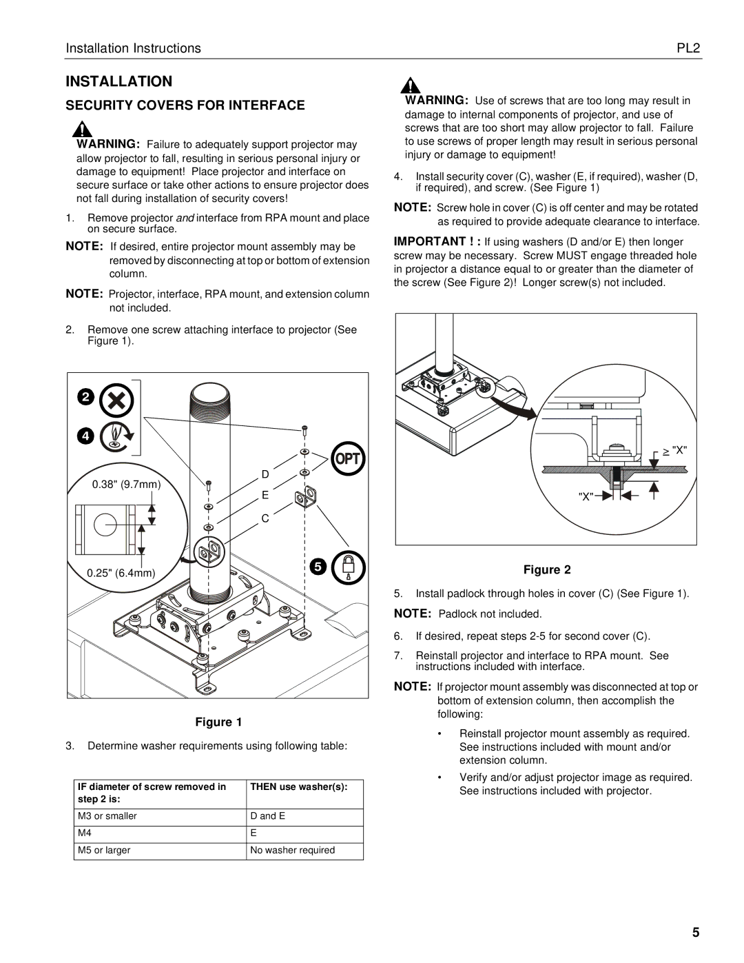
2.Remove one screw attaching interface to projector (See Figure 1).
2 |
| |
4 |
| |
0.38" (9.7mm) | D | |
E | ||
| ||
| C | |
0.25" (6.4mm) | 5 | |
|
Figure 1
3.Determine washer requirements using following table:
IF diameter of screw removed in | THEN use washer(s): |
step 2 is: |
|
|
|
M3 or smaller | D and E |
|
|
M4 | E |
|
|
M5 or larger | No washer required |
|
|
WARNING: Use of screws that are too long may result in damage to internal components of projector, and use of screws that are too short may allow projector to fall. Failure to use screws of proper length may result in serious personal injury or damage to equipment!
4.Install security cover (C), washer (E, if required), washer (D, if required), and screw. (See Figure 1)
NOTE: Screw hole in cover (C) is off center and may be rotated as required to provide adequate clearance to interface.
IMPORTANT ! : If using washers (D and/or E) then longer screw may be necessary. Screw MUST engage threaded hole in projector a distance equal to or greater than the diameter of the screw (See Figure 2)! Longer screw(s) not included.
> "X" |
"X" |
Figure 2
5.Install padlock through holes in cover (C) (See Figure 1).
NOTE: Padlock not included.
6.If desired, repeat steps
7.Reinstall projector and interface to RPA mount. See instructions included with interface.
NOTE: If projector mount assembly was disconnected at top or bottom of extension column, then accomplish the following:
•Reinstall projector mount assembly as required. See instructions included with mount and/or extension column.
•Verify and/or adjust projector image as required. See instructions included with projector.
5