RLT1 | Installation Instructions |
ASSEMBLY and INSTALLATION
INSPECT MOUNT BEFORE ASSEMBLY
1.Carefully inspect the mount components for shipping damage.
2.If any damage is apparent, call your carrier claims agent and do not continue with the installation until the carrier has reviewed the damage.
NOTE: Read all assembly instructions before starting the installation process.
To install interface brackets:
1.Place the left and right factory assembled interface bracket assemblies (20 and 30) on the back of the display.
(See Figure 1)
2.Position the interface bracket assemblies (20 and 30) with the tension knob on the tilt bracket faced toward the outside of the display. (See Figure 5)
3.Using the center hole on the interface bracket as a reference point, align the bracket with the center line of the display. (See Figure 2)
USE ONE OF THE HOLES OR TOP
OF SLOTS TO ALIGN BRACKETS
HORIZONTALLY
TILT BRACKET (LEFT SIDE SHOWN)
Figure 1
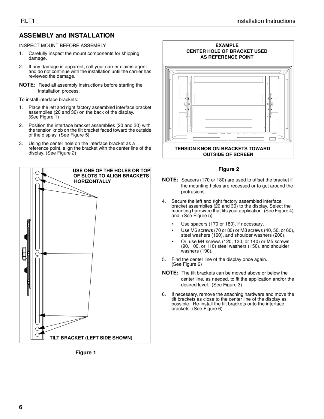
EXAMPLE
CENTER HOLE OF BRACKET USED
AS REFERENCE POINT
TENSION KNOB ON BRACKETS TOWARD
OUTSIDE OF SCREEN
Figure 2
NOTE: Spacers (170 or 180) are used to offset the bracket if the mounting holes are recessed or to get around the protrusions.
4.Secure the left and right factory assembled interface bracket assemblies (20 and 30) to the display. Select the mounting hardware that fits your application. (See Figure 4) and (See Figure 5)
•Use spacers (170 or 180), if necessary.
•Use M6 screws (70 or 80) or M8 screws (40, 50, or 60), steel washers (160), and shoulder washers (200).
•Or, use M4 screws (120, 130, or 140) or M5 screws (90, 100, or 110) steel washers (150), and shoulder washers (190).
5.Find the center line of the display once again. (See Figure 6)
NOTE: The tilt brackets can be moved above or below the center line, as needed, to fit the application and/or the desired level. (See Figure 3)
6.If necessary, remove the attaching hardware and move the tilt brackets as close to the center line of the display as possible.
6