RLT1 | Installation Instructions |
Wall Plate Installation
Lag Bolt Installation Instructions
To Install wall plate:
WARNING: It is the responsibility of the installer to verify that the structure to which the mount is anchored will safely support five times the combined load of all attached components and equipment.
1.Determine a suitable mounting location and lift the wall plate (10) into place.
2.Using a small nail or screw (not provided) in the center hole, lightly support the wall plate at the mounting location.
3.Level the wall plate (10) and drill pilot holes for anchoring the wall plate. If drilling into wood studs, use a 15/64” drill bit.
4.Using four 5/16” lag bolts (210) and 5/16” washers (220), install the wall plate on the wall.
5.Slide the latches to the outside.
Display Installation
To Install display:
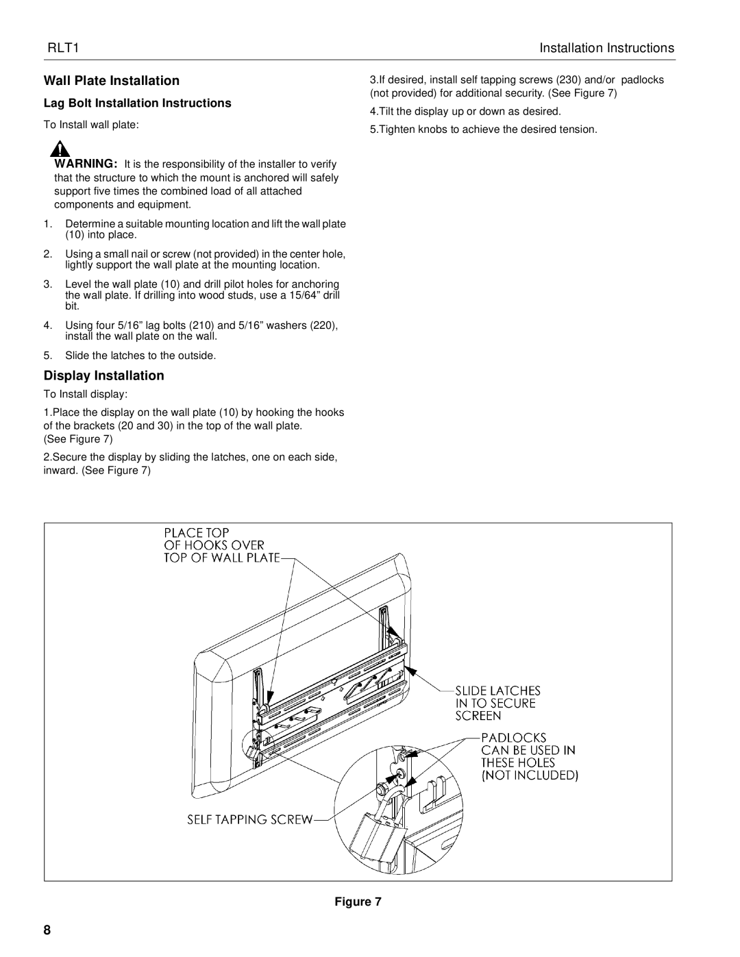
1.Place the display on the wall plate (10) by hooking the hooks of the brackets (20 and 30) in the top of the wall plate.
(See Figure 7)
2.Secure the display by sliding the latches, one on each side, inward. (See Figure 7)
3.If desired, install self tapping screws (230) and/or padlocks (not provided) for additional security. (See Figure 7)
4.Tilt the display up or down as desired.
5.Tighten knobs to achieve the desired tension.
Figure 7
8