WIRING
ELECTRIC SHOCK HAZARD. Any installation involving electric heaters must be performed by a qualified person and must be effectively grounded in accordance with the National Electrical Code to eliminate shock hazard.
4.Remove cover of conduit box for connections. Use either opening and plug the other with the plug provided.
5.In single phase units the heaters must be wired in parallel, com- bining L1 to L1, L2 to L2 and for 3 phase unit, L3 to L3.
6.
1.All wiring should be done in accordance with local codes and the National Electrical Code by a qualified person as defined in the NEC.
CAUTION: Use copper conductors only.
2.
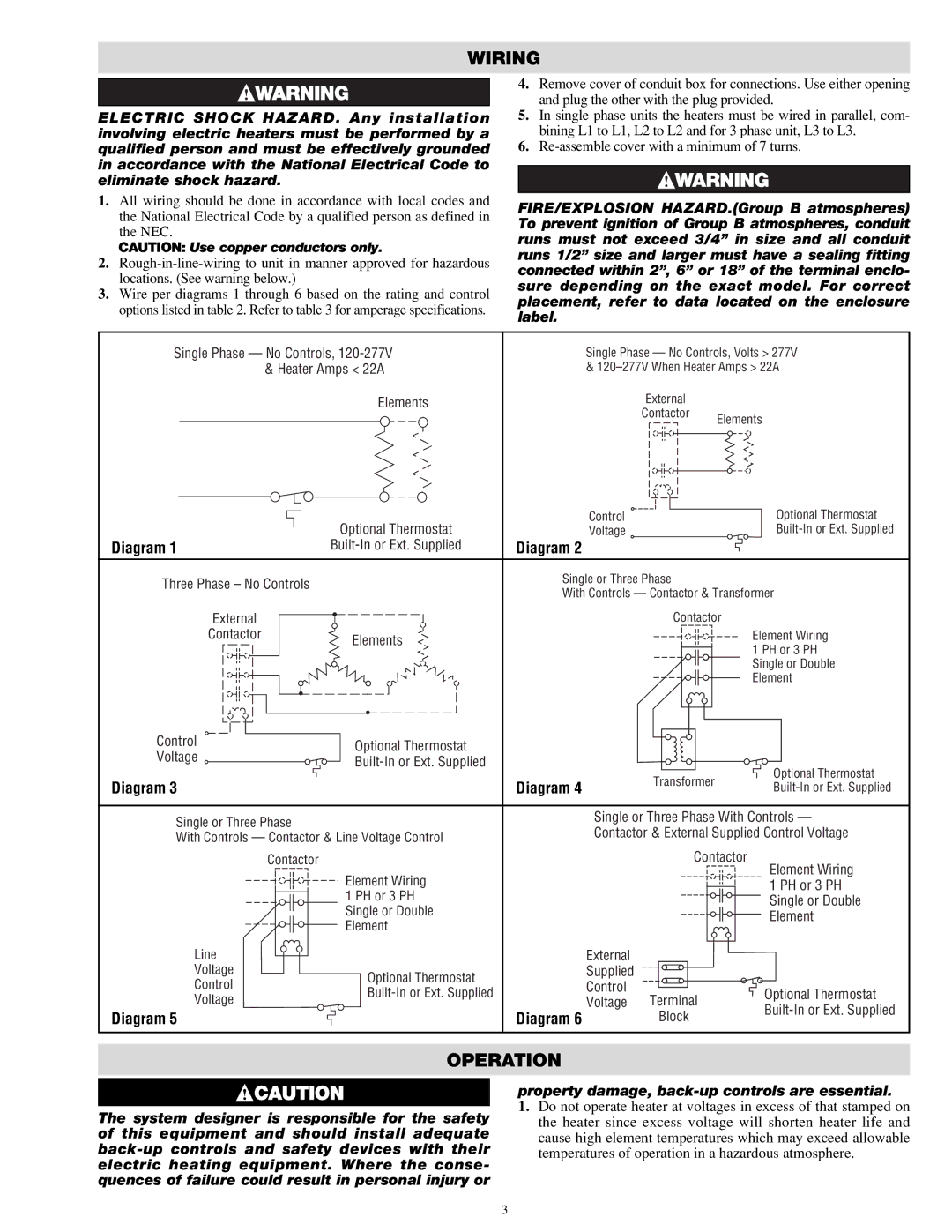
3.Wire per diagrams 1 through 6 based on the rating and control options listed in table 2. Refer to table 3 for amperage specifications.
FIRE/EXPLOSION HAZARD.(Group B atmospheres) To prevent ignition of Group B atmospheres, conduit runs must not exceed 3/4” in size and all conduit runs 1/2” size and larger must have a sealing fitting connected within 2”, 6” or 18” of the terminal enclo- sure depending on the exact model. For correct placement, refer to data located on the enclosure label.
Single Phase — No Controls, | Single Phase — No Controls, Volts > 277V | |
& Heater Amps < 22A | & | |
Elements | External |
|
| Contactor | Elements |
|
| |
| Optional Thermostat | Control |
| Optional Thermostat | |
| Voltage |
| |||
Diagram 1 | Diagram 2 |
|
| ||
Three Phase – No Controls |
| Single or Three Phase |
| ||
| With Controls — Contactor & Transformer | ||||
|
| ||||
External |
|
| Contactor |
| |
Contactor | Elements |
|
| Element Wiring | |
|
|
| 1 PH or 3 PH | ||
|
|
|
| ||
|
|
|
| Single or Double | |
|
|
|
| Element | |
Control | Optional Thermostat |
|
|
| |
Voltage |
|
|
| ||
|
|
| |||
|
|
| Optional Thermostat | ||
Diagram 3 |
| Diagram 4 | Transformer | ||
| |||||
|
| ||||
Single or Three Phase |
| Single or Three Phase With Controls — | |||
| Contactor & External Supplied Control Voltage | ||||
With Controls — Contactor & Line Voltage Control | |||||
|
|
| |||
Contactor |
|
| Contactor | Element Wiring | |
| Element Wiring |
|
| ||
|
|
| 1 PH or 3 PH | ||
| 1 PH or 3 PH |
|
| Single or Double | |
| Single or Double |
|
| ||
|
|
| Element | ||
| Element |
|
| ||
|
|
|
| ||
Line |
| External |
|
| |
Voltage | Optional Thermostat | Supplied |
|
| |
Control | Control |
|
| ||
| Optional Thermostat | ||||
Voltage | Voltage | Terminal | |||
| |||||
Diagram 5 |
| Diagram 6 | Block | ||
|
| ||||
OPERATION
The system designer is responsible for the safety of this equipment and should install adequate
property damage,
1.Do not operate heater at voltages in excess of that stamped on the heater since excess voltage will shorten heater life and cause high element temperatures which may exceed allowable temperatures of operation in a hazardous atmosphere.
3