Chromalox®
Installation, Operation
and
RENEWAL PARTS IDENTIFICATION
SERVICE REFERENCE
DIVISION 4 |
| SECTION CVEP | |
SALES | (Supersedes |
| |
REFERENCE | |||
161-302639-001
DATE JUNE, 2010
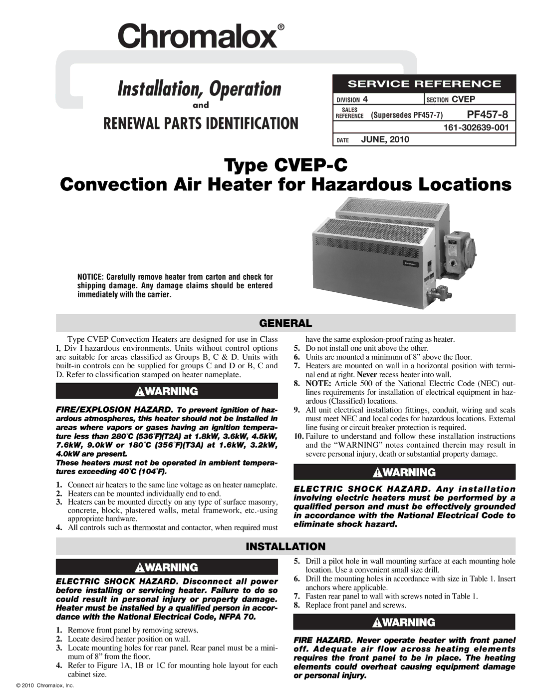
Type CVEP-C
Convection Air Heater for Hazardous Locations
NOTICE: Carefully remove heater from carton and check for shipping damage. Any damage claims should be entered immediately with the carrier.
GENERAL
Type CVEP Convection Heaters are designed for use in Class I, Div I hazardous environments. Units without control options are suitable for areas classified as Groups B, C & D. Units with
FIRE/EXPLOSION HAZARD. To prevent ignition of haz- ardous atmospheres, this heater should not be installed in areas where vapors or gases having an ignition tempera- ture less than 280˚C (536˚F)(T2A) at 1.8kW, 3.6kW, 4.5kW, 7.6kW, 9.0kW or 180˚C (356˚F)(T3A) at 1.6kW, 3.2kW, 4.0kW are present.
These heaters must not be operated in ambient tempera- tures exceeding 40˚C (104˚F).
1.Connect air heaters to the same line voltage as on heater nameplate.
2.Heaters can be mounted individually end to end.
3.Heaters can be mounted directly on any type of surface masonry, concrete, block, plastered walls, metal framework,
4.All controls such as thermostat and contactor, when required must
have the same
5.Do not install one unit above the other.
6.Units are mounted a minimum of 8” above the floor.
7.Heaters are mounted on wall in a horizontal position with termi- nal end at right. Never recess heater into wall.
8.NOTE: Article 500 of the National Electric Code (NEC) out- lines requirements for installation of electrical equipment in haz- ardous (Classified) locations.
9.All unit electrical installation fittings, conduit, wiring and seals must meet NEC and local codes for hazardous locations. External line fusing or circuit breaker protection is required.
10.Failure to understand and follow these installation instructions and the “WARNING” notes contained therein may result in severe personal injury, death or substantial property damage.
ELECTRIC SHOCK HAZARD. Any installation involving electric heaters must be performed by a qualified person and must be effectively grounded in accordance with the National Electrical Code to eliminate shock hazard.
INSTALLATION
ELECTRIC SHOCK HAZARD. Disconnect all power before installing or servicing heater. Failure to do so could result in personal injury or property damage. Heater must be installed by a qualified person in accor- dance with the National Electrical Code, NFPA 70.
1.Remove front panel by removing screws.
2.Locate desired heater position on wall.
3.Locate mounting holes for rear panel. Rear panel must be a mini- mum of 8” from the floor.
4.Refer to Figure 1A, 1B or 1C for mounting hole layout for each cabinet size.
5.Drill a pilot hole in wall mounting surface at each mounting hole location. Use a convenient small size drill.
6.Drill the mounting holes in accordance with size in Table 1. Insert anchors where applicable.
7.Fasten rear panel to wall with screws noted in Table 1.
8.Replace front panel and screws.
FIRE HAZARD. Never operate heater with front panel off. Adequate air flow across heating elements requires the front panel to be in place. The heating elements could overheat causing equipment damage or personal injury.
© 2010 Chromalox, Inc.