Chromalox®
Installation, Operation
and
RENEWAL PARTS IDENTIFICATION
|
|
|
|
|
|
|
|
|
|
|
|
|
|
|
|
|
|
DIVISION 4 |
|
|
| SECTION LUH | |
SALES | (Supersedes |
| |||
REFERENCE | |||||
|
|
|
|
| |
DATE JANUARY, 2007
Thermostat Kits
Model Number
Model Number
For field installation only in
SPECIFICATIONS
1.Temperature Range: 40˚F to 90˚F.
2.Differential: 5˚F.
3.
LO![]() HI
HI
ChromaloxR
OFF
GENERAL
The following procedure contains instructions for installing ther- mostat kits
ELECTRIC SHOCK HAZARD. Disconnect all power before installing thermostat kit. Failure to do so could result in personal injury or property damage. Thermostat kit must be installed by a qualified per- son in accordance with the National Electrical Code, NFPA 70.
INSTALLATION
Step 1
1.Verify that the thermostat kit is compatible with your heater.
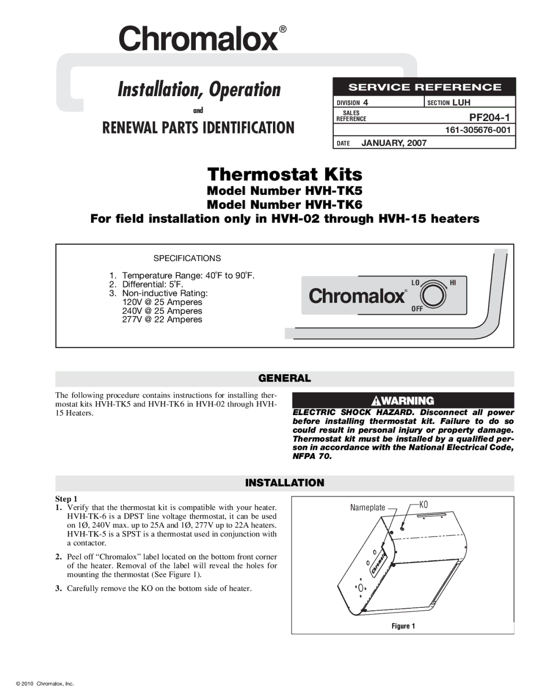
2.Peel off “Chromalox” label located on the bottom front corner of the heater. Removal of the label will reveal the holes for mounting the thermostat (See Figure 1).
3.Carefully remove the KO on the bottom side of heater.
Nameplate ![]() KO
KO
Figure 1
© 2010 Chromalox, Inc.