WIRING DIAGRAMS (cont’d.)
Figure 5
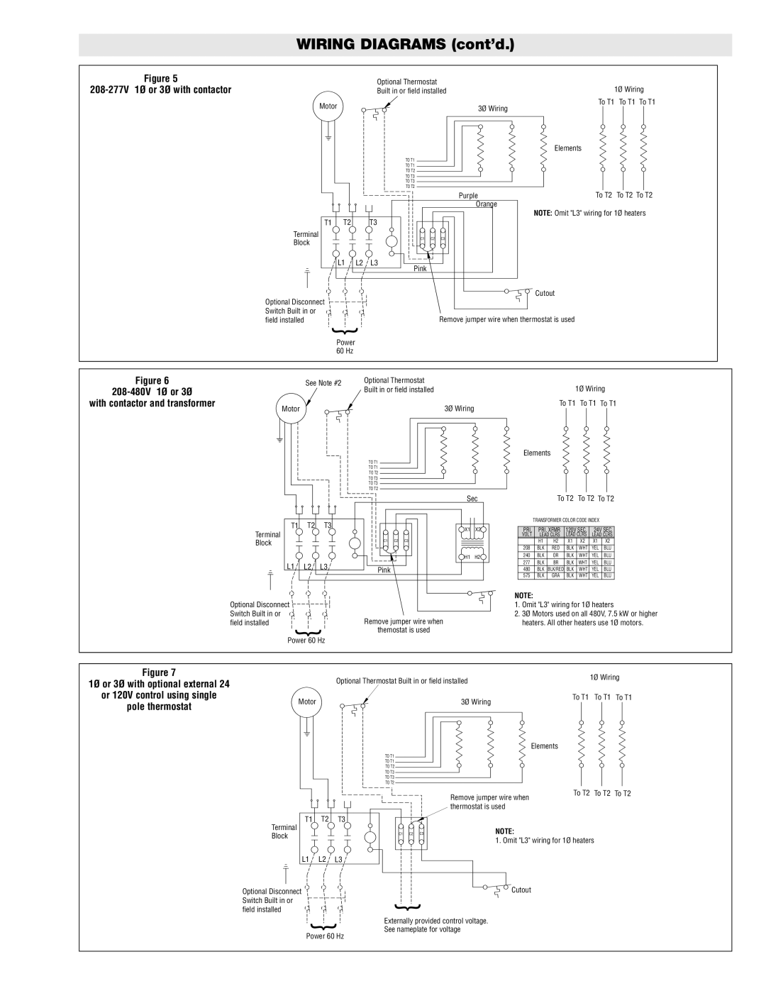
208-277V 1Ø or 3Ø with contactor
Optional Thermostat
Built in or field installed
Motor
TO T1
TO T1
TO T2
TO T3
TO T3
TO T2
1Ø Wiring
To T1 To T1 To T1
3Ø Wiring
Elements
|
|
|
|
| Purple | To T2 To T2 To T2 |
|
|
|
|
| Orange | NOTE: Omit "L3" wiring for 1Ø heaters |
|
|
|
|
|
| |
T1 | T2 |
| T3 |
|
|
|
Terminal |
|
| C1 | C2 | C3 |
|
Block |
|
|
| |||
|
|
|
|
|
| |
| L1 | L2 | L3 |
|
|
|
|
|
| Pink |
|
|
|
Optional Disconnect |
|
|
|
|
| Cutout |
|
|
|
|
|
| |
Switch Built in or |
|
|
|
| Remove jumper wire when thermostat is used | |
field installed |
|
|
|
| ||
|
|
|
| { |
|
|
|
|
|
|
|
|
|
|
| Power |
|
|
|
|
|
|
|
|
|
|
| 60 Hz |
|
|
|
|
|
|
|
|
|
|
|
|
|
|
|
|
|
|
|
|
|
|
|
|
|
|
|
|
|
|
|
Figure 6 |
|
| See Note #2 | Optional Thermostat |
| 1Ø Wiring | |||||
|
|
|
| Built in or field installed |
| ||||||
with contactor and transformer |
|
|
|
| To T1 To T1 | To T1 | |||||
|
| Motor |
|
| 3Ø Wiring |
|
|
|
|
| |
|
|
|
|
|
|
|
|
| |||
|
|
|
|
|
|
|
|
|
|
|
|
|
|
|
|
|
|
|
|
|
|
|
|
|
|
|
|
|
|
|
|
|
|
|
|
Elements
TO T1
TO T1
TO T2
TO T3
TO T3
TO T2
Sec | To T2 To T2 To T2 |
T1 | T2 | T3 |
Terminal |
|
|
Block |
|
|
L1 | L2 | L3 |
Optional Disconnect Switch Built in or field installed
{
Power 60 Hz
![]() X1 X2
X1 X2![]()
C1 | C2 | C3 |
![]() H1 H2
H1 H2![]()
Pink
Remove jumper wire when
themostat is used
TRANSFORMER COLOR CODE INDEX
PRI. | PRI. XFMR | 120V SEC. | 24V SEC. | |||
VOLT | LEAD CLRS | LEAD CLRS | LEAD CLRS | |||
| H1 | H2 | X1 | X2 | X1 | X2 |
208 | BLK | RED | BLK | WHT | YEL | BLU |
240 | BLK | OR | BLK | WHT | YEL | BLU |
277 | BLK | BR | BLK | WHT | YEL | BLU |
480 | BLK | BLK/RED | BLK | WHT | YEL | BLU |
575 | BLK | GRA | BLK | WHT | YEL | BLU |
NOTE:
1.Omit "L3" wiring for 1Ø heaters
2.3Ø Motors used on all 480V, 7.5 kW or higher heaters. All other heaters use 1Ø motors.
Figure 7 |
| Optional Thermostat Built in or field installed | 1Ø Wiring | |
1Ø or 3Ø with optional external 24 |
| |||
|
|
| ||
or 120V control using single | Motor | 3Ø Wiring | To T1 To T1 | To T1 |
pole thermostat |
|
| ||
|
|
|
| |
|
|
| Elements |
|
|
| TO T1 |
|
|
|
| TO T1 |
|
|
|
| TO T2 |
|
|
|
| TO T3 |
|
|
|
| TO T3 |
|
|
|
| TO T2 |
|
|
|
|
|
|
|
|
|
|
|
|
|
|
|
|
|
|
|
|
|
|
|
|
T1 |
| T2 |
| T3 |
|
|
| |||
|
|
|
|
|
|
|
|
|
|
|
Terminal
Block
L1 L2 L3
Optional Disconnect
Switch Built in or
C1 C2
C3
Remove jumper wire when | To T2 | To T2 To T2 |
|
|
thermostat is used
NOTE:
1. Omit "L3" wiring for 1Ø heaters
![]()
![]() Cutout
Cutout
field installed
{
Power 60 Hz
{
Externally provided control voltage. See nameplate for voltage