INSTALLATION (cont’d.)
Step 2 (Figure 2)
1.Remove (2) screws on cover and open cover.
2.Feed thermostat capillary (be careful not to kink or make any sharp bends) out through the hole made in step 1.
3.Mount body of thermostat to front of heater case using the (2)
| SHEET METAL |
| SCREW |
| CLAMP |
| THERMOSTAT |
| BULB |
| RUBBER |
| GROMMET |
KNOB |
|
LABEL FOR | |
THERMOSTAT | HEAD |
| SCREW |
| THERMOSTAT |
| BODY |
| LEADWIRES |
Figure 2 |
|
Step 3 (Figure 3)
1.Attach thermostat bulb to case using the (2) clamps and screws.
2.Make a slit in the rubber grommet and insert the grommet over the capillary.
3.Install the grommet into the hole in the case.
Figure 3 |
Step 4
1.For
For
For
2.Inspect wiring to make sure it matches the appropriate wiring diagram.
3.Close heater cover and reattach screws.
WIRING DIAGRAMS
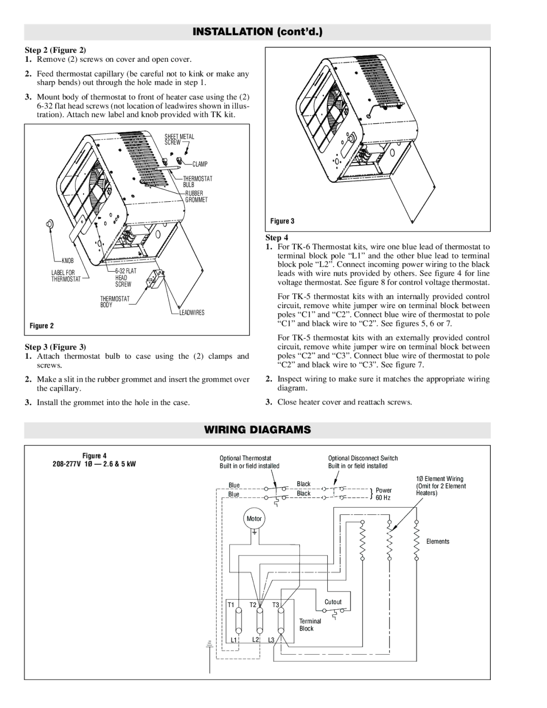
Figure 4
208-277V 1Ø — 2.6 & 5 kW
Optional Thermostat |
| Optional Disconnect Switch |
| ||
Built in or field installed |
| Built in or field installed |
| ||
Blue | Black |
|
| 1Ø Element Wiring | |
} | Power | (Omit for 2 Element | |||
Blue | Black | Heaters) | |||
60 Hz | |||||
|
| ||||
Motor
Elements
T1 | T2 | T3 | Cutout |
| |||
|
|
| Terminal |
|
|
| Block |
L1 | L2 | L3 |
|