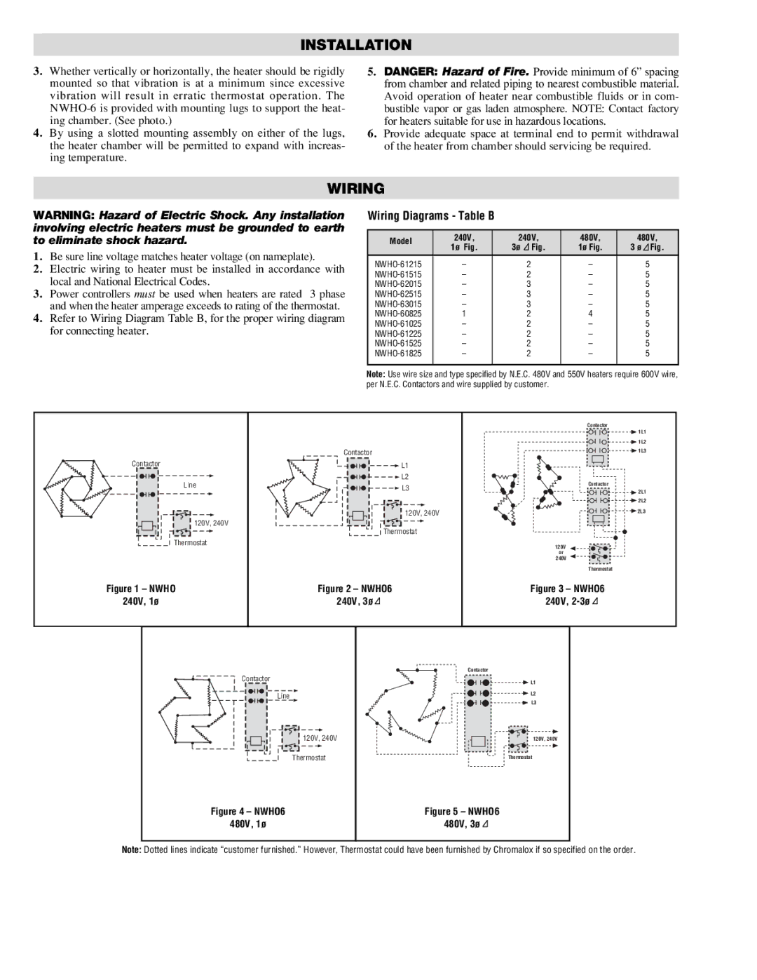
NWHO-6 specifications
The Chromalox NWHO-6 is an innovative heating solution designed for various industrial and commercial applications. Built with advanced features and robust technologies, this heating element enhances efficiency and performance, making it a go-to choice for many organizations.One of the primary features of the NWHO-6 is its exceptional durability. Constructed from high-quality materials, it is engineered to withstand harsh environments, including exposure to moisture, chemicals, and extreme temperatures. This resilience ensures a longer operational life, reducing the need for frequent replacements and maintenance.
The NWHO-6 utilizes advanced heating technologies, including flexible heating configurations. This allows users to customize the output based on specific requirements, making the unit highly versatile. Whether used for process heating, freeze protection, or temperature maintenance, the NWHO-6 adapts seamlessly to various applications.
Energy efficiency is another key characteristic of the Chromalox NWHO-6. The design incorporates innovative heat distribution mechanisms that optimize energy consumption while providing consistent heating output. This efficiency not only lowers operational costs but also contributes positively to environmental sustainability by reducing energy waste.
Safety is paramount in industrial heating solutions, and the NWHO-6 excels in this area as well. With built-in safety features such as thermal overload protection and a reliable control system, the unit minimizes risks associated with overheating or failure. This focus on safety helps to protect both personnel and equipment, ensuring a secure working environment.
The NWHO-6 also features user-friendly integration options. It can be easily implemented into existing systems, offering compatibility with various industrial controls and automation systems. This simplicity in integration makes it ideal for retrofitting or upgrading heating solutions without extensive modifications.
Another advantage is the compact design of the NWHO-6, which allows for easy installation in tight spaces. The streamlined profile ensures that even in crowded environments, the heating unit can be effectively utilized without compromising operational space.
In conclusion, the Chromalox NWHO-6 stands out as a superior heating solution, characterized by its durability, energy efficiency, safety features, and ease of integration. Whether in manufacturing, food processing, or any other industrial sector, the NWHO-6 provides reliable and effective heating, making it an essential component for a wide array of applications. Organizations seeking to enhance their heating solutions will find the NWHO-6 to be an invaluable asset, driving operational efficiency and reducing long-term costs.

